22. FA TRANSPARENT FUNCTION
22.6 Personal Computer Side Setting
22 - 65
17
ROBOT
CONTROLLER
CONNECTION
18
CNC CONNECTION
19
GOT MULTI-DROP
CONNECTION
20
MULTIPLE-GT14, GT12,
GT11, GT10
CONNECTION FUNCTION
21
MULTI-CHANNEL
FUNCTION
22
FA TRANSPARENT
FUNCTION
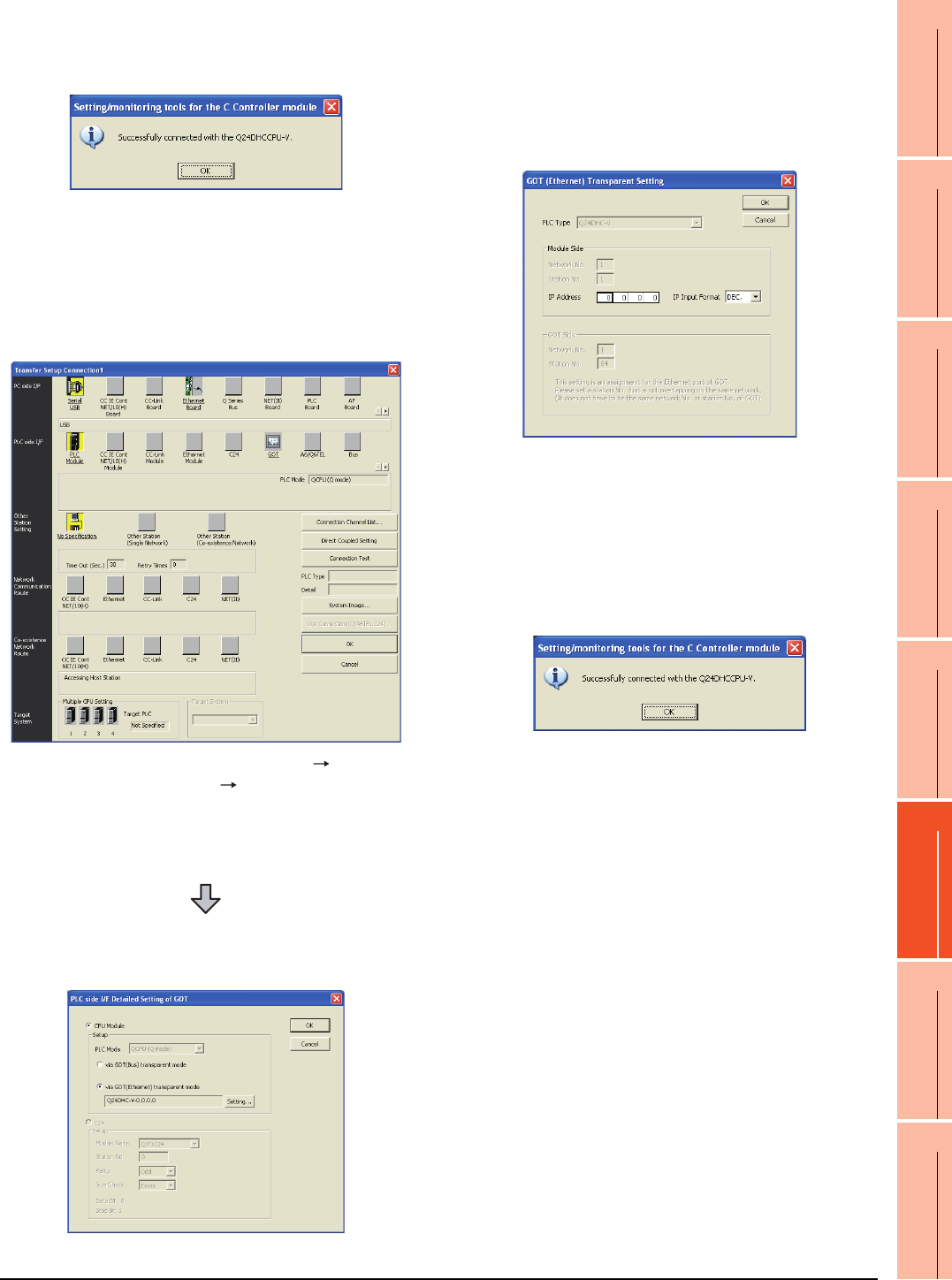
(2) When connecting the GOT and PLC in Ethernet
communication
5. Mark the [via GOT(Bus) transparent mode]
checkbox on the [CPU side I/F Detailed Setting of
GOT] screen.
6. The screen returns to [Transfer Setup]. Click
[Connection Test] to check if Setting/Monitoring tool
for C Controller module has been connected to the
motion controller (Q mode).
1. Click the Connection Destination view
[Connection Destination] [(Connection target
data name)] in the Navigation window of MT Setting/
Monitoring tool for C Controller module.
2. The [Transfer Setup] is displayed.
3. Set the [Transfer Setup]:
PLC side I/F : GOT
Other station : No specification
4. Double-click [GOT] of the CPU side I/F to display
[CPU side I/F Detailed Setting of GOT].
5. Mark the [via GOT(Ethernet) transparent mode]
checkbox on the [CPU side I/F Detailed Setting of
GOT] screen.
6. By clicking [Set], the [GOT (Ethernet) Transparent
Setting] is displayed.
Here, set the C Controller module (Q24DHCCPU-
V), which is firstly connected via a GOT.
7. Specify the IP address for [IP address] same as the
IP address assigned to the C Controller module
(Q24DHCCPU-V).
8. The screen returns to [Transfer Setup]. Click
[Connection Test] to check if Setting/Monitoring tool
for C Controller module has been connected to the
C Controller module (Q24DHCCPU-V).


