


16 - 16
16. SERVO AMPLIFIER CONNECTION
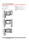
16.5 Setting on Servo Amplifier Side
16.5.3 Connecting to the
MELSERVO-J4,J3 Series
POINTPOINTPOINT
MELSERVO-J4, J3 Series
For details of the MELSERVO-J4, J3 Series, refer to
the following manual.
See the technical manual for the MELSERVO-
J4, J3 Series servo amplifiers.
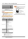
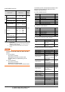
Parameters of MELSERVO-J4, J3 Series
Enter the parameters of the MELSERVO-J4, J3 Series.
*1 Avoid duplication of the station No. with any of the other
axes.
*2 Specify the same transmission speed as that of the GOT.
For the transmission speed setting on the GOT side, refer to
the following.
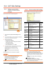
16.4.1 Setting communication interface
(Communication settings)
POINTPOINTPOINT
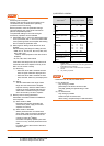
(1) Parameter setting
Set the parameter at the pushbutton switch
provided on the operation section of the servo
amplifier or setup software.
(2) When changing the parameter
Turn off then on the servo amplifier to be effective
the new parameter.
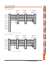
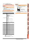
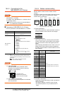
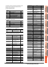
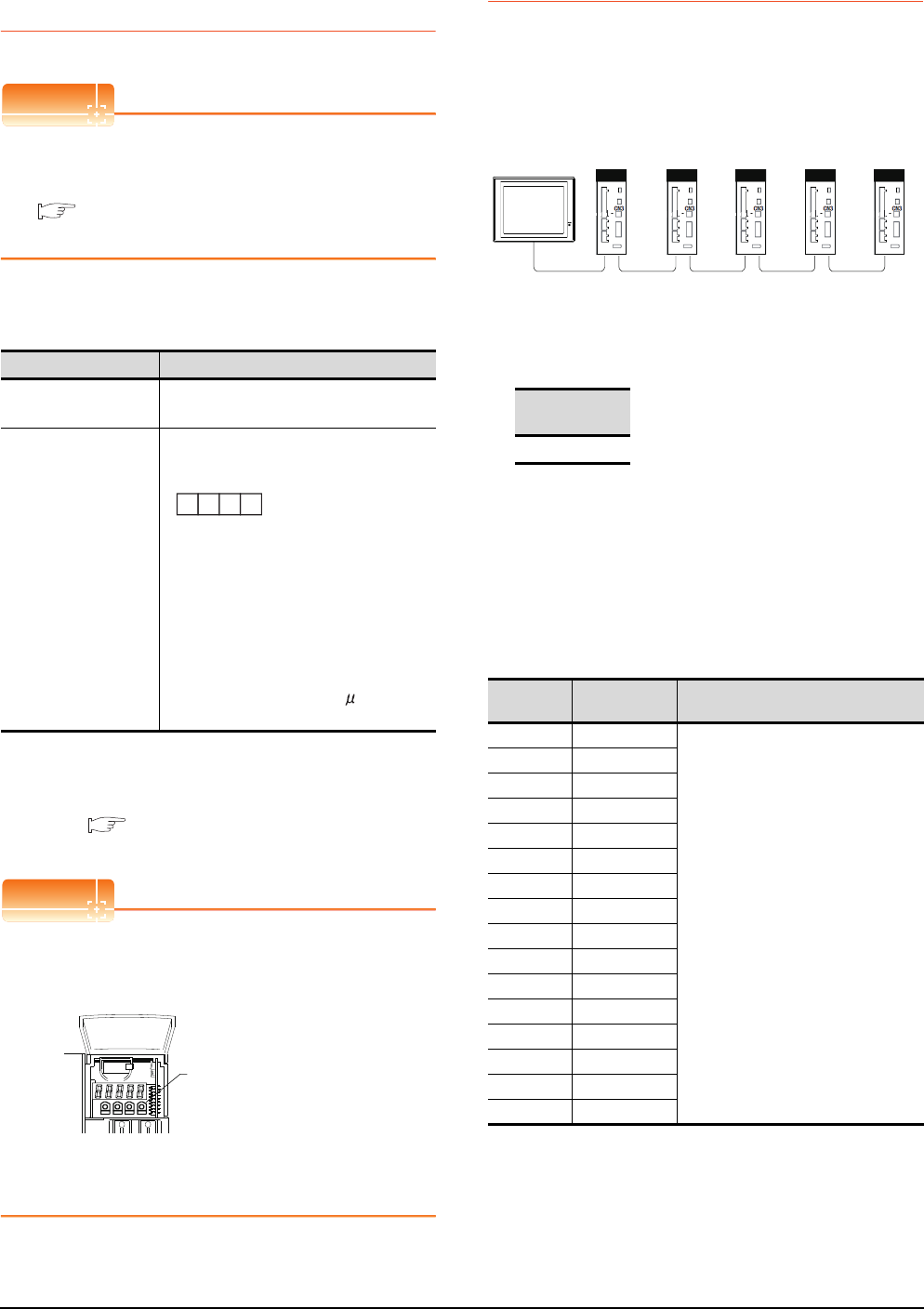
16.5.4 Station number setting
Set each station number so that no station number
overlaps.
The station number can be set without regard to the cable
connection order. There is no problem even if station
numbers are not consecutive.
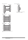
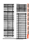
(1) Direct specification
When setting the device, specify the station number of
the servo amplifier of which data is to be changed.
(2) Indirect specification
When setting the device, indirectly specify the station
number of the inverter of which data is to be changed
using the 16-bit GOT internal data register (GD10 to
GD25).
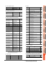
When specifying the station No. from 100 to 115 on GT
Designer3,the value of GD10 to GD25 compatible to
the station No.specification will be the station No.of the
servo amplifier.
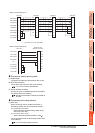
(3) All station specification
Target station differs depending on write-in operation or
read-out operation.
• For write-in operation, all station will be a target.
• For read-out operation, only one station will be a
target.
Item Set value
Basic parameter
No. PC20
Station number setting: 0 to 31
(Default: 0)
*1
Basic parameter
No. PC21
Serial communication function selection
(Default: 0000)
(1)Serial communication baud rate selection
*2
0: 9600bps
1: 19200bps
2: 38400bps
3: 57600bps
4: 115200bps
(2)Communication response delay time
selection
0: Invalid
1: Valid (Response after 800 s or longer
delay)
(2) (1)
Basic parameter No. PC21
MODE UP DOWN
SET
Pushbutton switch
provided on the operation
section of the servo amplifier
Specification
range
0 to 31
Specification
station NO.
Compatible
device
Setting range
100 GD10
0 to 31
For the setting other than the above, a
communication timeout error will occur.
101 GD11
102 GD12
103 GD13
104 GD14
105 GD15
106 GD16
107 GD17
108 GD18
109 GD19
110 GD20
111 GD21
112 GD22
113 GD23
114 GD24
115 GD25
Station
NO.3
Station
NO.0
Station
NO.1
Station
NO.21
Station
NO. 6
Examples of station number setting
GOT