4 - 6
4. HOW TO MONITOR REDUNTANT SYSTEM
*1 To monitor the control system after the system switching without the Q redundant setting, change the cable connection from the
PLC CPU in the previous control system to the control system after system switching.
*2 To monitor the control system after the system switching without the Q redundancy setting, refer to the following.
4.10Switch the Monitor Target to the Control System Using the Script Function
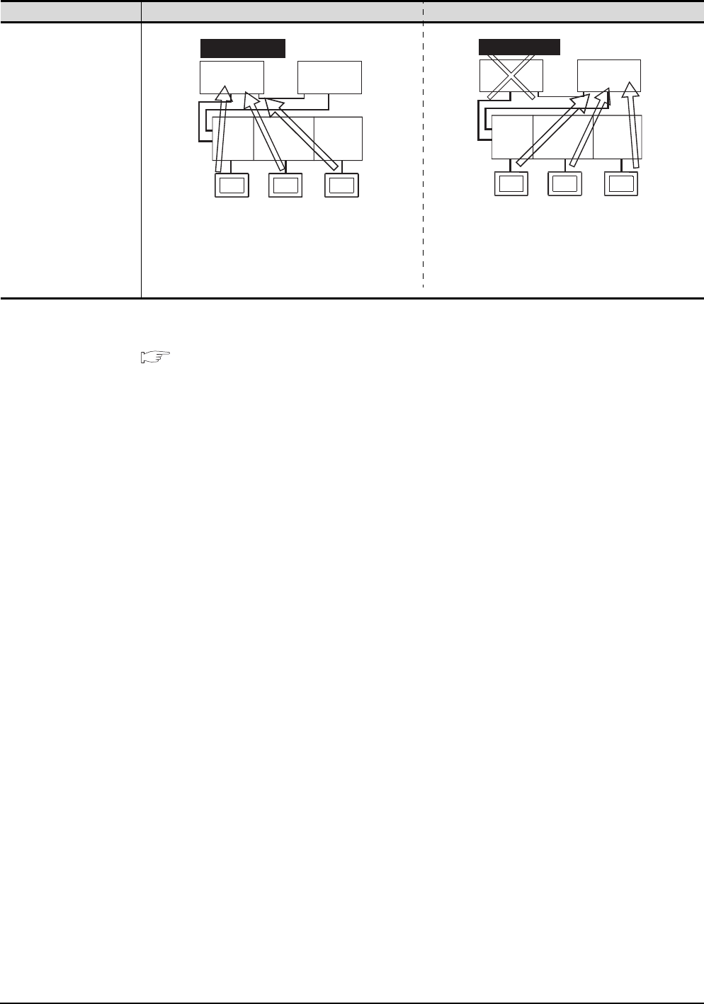
Connection type Before system switching After system switching
• Computer link connection
(Serial communication
module mounted on the
redundant type extension
base unit)
• Ethernet connection
(Ethernet module mounted
on the redundant type
extension base unit)
• CC-Link connection
(intelligent device station)
(CC-Link module mounted
on the redundant type
extension base unit)
• CC-Link connection (Via
G4)
(CC-Link module mounted
on the redundant type
extension base unit)
CC-Link
module
Serial
communication
module
Ethernet
module
CC-Link
connection
Computer link
connection
Ethernet
connection
GOT3
GOT2
GOT1
Control system
Station
No. 1
Station
No. 2
CC-Link
module
Serial
communication
module
Ethernet
module
CC-Link
connection
Computer link
connection
Ethernet
connection
GOT3
GOT2
GOT1
Control system
Station
No. 1
Standby system
Station
No. 2


