


8. ETHERNET CONNECTION
8.4 PLC Side Setting
8 - 43
1
PREPARATORY
PROCEDURES FOR
MONITORING
2
DEVICE RANGE
THAT CAN BE SET
3
ACCESS RANGE
FOR MONITORING
4
HOW TO MONITOR
REDUNTANT
SYSTEM
5
BUS CONNECTION
6
DIRECT
CONNECTION TO
CPU
7
COMPUTER LINK
CONNECTION
8
ETHERNET
CONNECTION
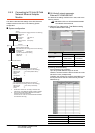
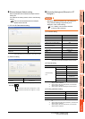
(2) Ethernet setting
POINTPOINTPOINT
[Controller Setting] and [Ethernet] of GT Designer3
For [Controller Setting] and [Ethernet] of GT
Designer3, refer to the following.
8.3.1 Setting communication interface
(Communication settings)
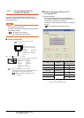
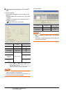
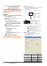
Checking communication state of CNC C70
(1) When using the Command Prompt of Windows
.
Execute a Ping command at the Command Prompt of
Windows
.
(a) When normal communication
C:\>Ping 192.168.0.19
Reply from 192.168.0.19: bytes=32 time<1ms
TTL=64
(b) When abnormal communication
C:\>Ping 192.168.0.19
Request timed out.
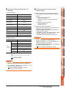
(2) When abnormal communication
At abnormal communication, check the followings and
execute the Ping command again.
• Mounting condition of CNC C70
• Cable connecting condition
• Switch settings and network parameter settings
• Operation state of PLC CPU (faulty or not)
• IP address of the CNC C70 specified for the Ping
command
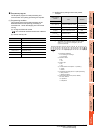
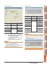
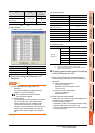
Item Set value
Ethernet
setting No.1
Host *
N/W No. 1
PLC No. 2
Type Q17nNC
IP address 192.168.0.19
Port No. 5001 (fixed)
Communication UDP (fixed)