


16 - 36
16. SERVO AMPLIFIER CONNECTION
16.6 Device Range that Can Be Set
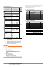
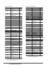
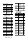
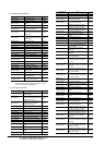
(d) Basic setting parameter
*1 For the parameters prefixed by an asterisk (*), setting
becomes effective when the power is turned off once and
back on after setting the parameter data.
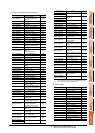
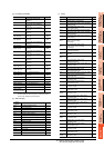
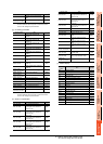
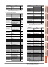
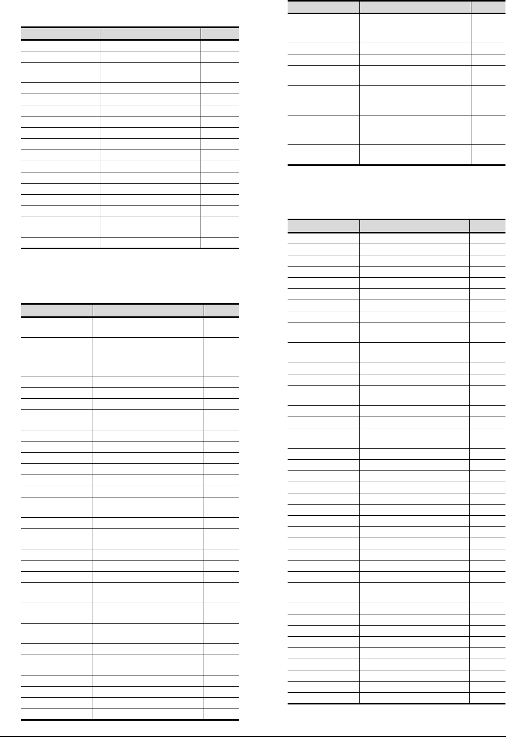
(e) Gain filter parameter
*1 For the parameters prefixed by an asterisk (*), setting
becomes effective when the power is turned off once and
back on after setting the parameter data.
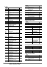
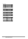
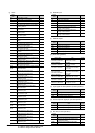
(f) Extension setting parameter
(Continued to next page)
Device name Item
Symbol
*1
PA1, PA1001 Control mode *STY
PA2, PA1002 Regenerative brake option *REG
PA3, PA1003
Absolute position detection
system
*ABS
PA4, PA1004 Function selection A-1 *AOP1
PA5, PA1005 Feeding function selection *FTY
PA6, PA1006 Electronic gear numerator *CMX
PA7, PA1007 Electronic gear denominator *CDV
PA8, PA1008 Auto tuning mode ATU
PA9, PA1009 Auto tuning response RSP
PA10, PA1010 In-position range INP
PA11, PA1011 Forward torque limit TLP
PA12, PA1012 Reverses torque limit TLN
PA13, PA1013 For manufacturer setting ―
PA14, PA1014 Rotation direction selection *POL
PA15, PA1015 Encoder output pulses *ENR
PA16 to PA18,
PA1016 to PA1018
For manufacturer setting ―
PA19, PA1019 Parameter block *BLK
Device name Item
Symbol
*1
PB1, PB1001
Adaptive tuning mode
(Adaptive filter II)
FILT
PA2, PB1002
Vibration suppression control filter
tuning mode
(advanced vibration suppression
control)
VRFT
PB3, PB1003 For manufacturer setting ―
PB4, PB1004 Feed forward gain FFC
PB5, PB1005 For manufacturer setting ―
PB6, PB1006
Ratio of load inertia moment to
servo motor inertia moment
GD2
PB7, PB1007 Model control gain PG1
PB8, PB1008 Position loop gain PG2
PB9, PB1009 Speed loop gain VG2
PB10, PB1010 Speed integral compensation VIC
PB11, PB1011 Speed differential compensation VDC
PB12, PB1012 For manufacturer setting ―
PB13, PB1013
Machine resonance suppression
filter 1
NH1
PB14, PB1014 Notch form selection 1 NHQ1
PB15, PB1015
Machine resonance suppression
filter 2
NH2
PB16, PB1016 Notch form selection 2 NHQ2
PB17, PB1017 For manufacturer setting ―
PB18, PB1018 Low-pass filter setting LPF
PB19, PB1019
Vibration suppression control
vibration frequency setting
VRF1
PB20, PB1020
Vibration suppression control
resonance frequency setting
VRF2
PB21 to PB22,
PB1021 to PB1022
For manufacturer setting ―
PB23, PB1023 Low-pass filter selection VFBF
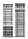
PB24, PB1024
Slight vibration suppression
control selection
*MVS
PB25, PB1025 For manufacturer setting ―
PB26, PB1026 Gain changing selection *CDP
PB27, PB1027 Gain changing condition CDL
PB28, PB1028 Gain changing time constant CDT
PB29, PB1029
Gain changing, Ratio of load
inertia moment to servo motor
inertia moment
GD2B
PB30, PB1030 Gain changing, Position loop gain PG2B
PB31, PB1031 Gain changing, Speed loop gain VG2B
PB32, PB1032
Gain changing, Speed integral
compensation
VICB
PB33, PB1033
Gain changing, Vibration
suppression control vibration
frequency setting
VRF1B
PB34, PB1034
Gain changing, Vibration
suppression control resonance
frequency setting
VRF2B
PB35 to PB45,
PB1035 to PB1045
For manufacturer setting ―
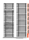
Device name Item
Symbol
*1
PC1, PC1001 For manufacturer setting ―
PC2, PC1002 Home position return type *ZTY
PC3, PC1003 Direction of home position return *ZDIR
PC4, PC1004 Home position return speed ZRF
PC5, PC1005 Creep speed CRF
PC6, PC1006 Home position shift distance ZST
PC7, PC1007
Home position return position data
*ZPS
PC8, PC1008
Moving distance after proximity dog
DCT
PC9, PC1009
Hold time home position return
hold time
ZTM
PC10, PC1010
Hold time home position return
torque limit value
ZTT
PC11, PC1011 Rough match output range CRP
PC12, PC1012 Jog speed JOG
PC13, PC1013
S-pattern acceleration/
deceleration time constant
*STC
PC14, PC1014 Backlash compensation *BKC
PC15, PC1015 For manufacturer setting ―
PC16, PC1016
Electromagnetic brake sequence
output
MBR
PC17, PC1017 Zero speed ZSP
PC18, PC1018 Alarm history clear *BPS
PC19, PC1019 Encoder output pulse selection *ENRS
PC20, PC1020 Station number setting *SNO
PC21, PC1021
Communication function selection
*SOP
PC22, PC1022 Function selection C-1 *COP1
PC23, PC1023 For manufacturer setting ―
PC24, PC1024 Function selection C-3 *COP3
PC25, PC1025 For manufacturer setting ―
PC26, PC1026 Function selection C-5 *COP5
PC27, PC1027 For manufacturer setting ―
PC28, PC1028 Function selection C-7 *COP7
PC29 to PC30,
PC1029 to PC1030
For manufacturer setting ―
PC31, PC1031 Software limit + Low LMPL
PC32, PC1032 Software limit + High LMPH
PC33, PC1033 Software limit - Low LMNL
PC34, PC1034 Software limit - High LMNH
PC35, PC1035 Internal torque limit 2 TL2
PC36, PC1036 Status display selection *DMD
PC37, PC1037
Position range output address + Low
*LPPL
PC38, PC1038
Position range output address + High
*LPPH
PC39, PC1039
Position range output address - Low
*LNPL
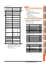
Device name Item
Symbol
*1