


7. COMPUTER LINK CONNECTION
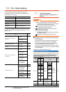
7.5 PLC Side Setting
7 - 23
1
PREPARATORY
PROCEDURES FOR
MONITORING
2
DEVICE RANGE
THAT CAN BE SET
3
ACCESS RANGE
FOR MONITORING
4
HOW TO MONITOR
REDUNTANT
SYSTEM
5
BUS CONNECTION
6
DIRECT
CONNECTION TO
CPU
7
COMPUTER LINK
CONNECTION
8
ETHERNET
CONNECTION
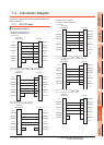
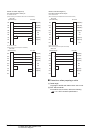
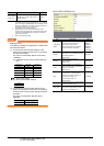
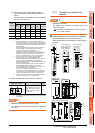
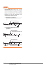
(2) When connecting to the CH2 side
*1 The module operates under the following transmission
specifications.
*2 The serial communication module operates at the
transmission speed set on the GOT.
*3 When the value of switch setting is other than "0", the setting
of [Format] and [Transmission Speed] on the GOT side are
required to be changed.
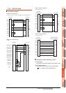
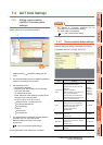
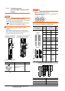
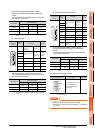
7.4.2 Communication detail settings
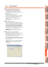
POINTPOINTPOINT
(1) When the [intelligent function module switch
setting] has been set
After writing PLC parameters to the PLC CPU,
turn the PLC CPU OFF then back ON again, or
reset the PLC CPU.
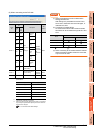
(2) Connection of multiple GOTs
To some serial communication module models,
two GOTs can be connected using both CH1 and
CH2.
: 2 GOTs connectable, : 1 GOT connectable, -: Not applicable
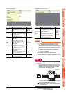
(3) When connecting to the modem interface module
When the modem interface module is connected,
only CH2 can be used.
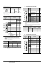
Switch
No.
Bit
Description
Set
value
*3
Positi
on
Specifi
ed
value
Switch 3
b0 OFF
CH2
transmiss
ion
settings
*1
Operation
setting
(Operates
according
to the GOT
side
specificatio
ns.)
0000
H
b1 OFF Data bit
b2 OFF
Parity
bit
b3 OFF
Even/odd
parity
b4 OFF Stop bit
b5 OFF
Sum
check
code
b6 OFF
Write
during
RUN
b7 OFF
Setting
modifica-
tions
b8 to
b15
―
CH2 transmission
speed setting
*2
Switch 4 ―
CH2 Communication
protocol setting
GX
Developer
connection
0000H
Switch 5 ― Station number setting 0th station 0000H
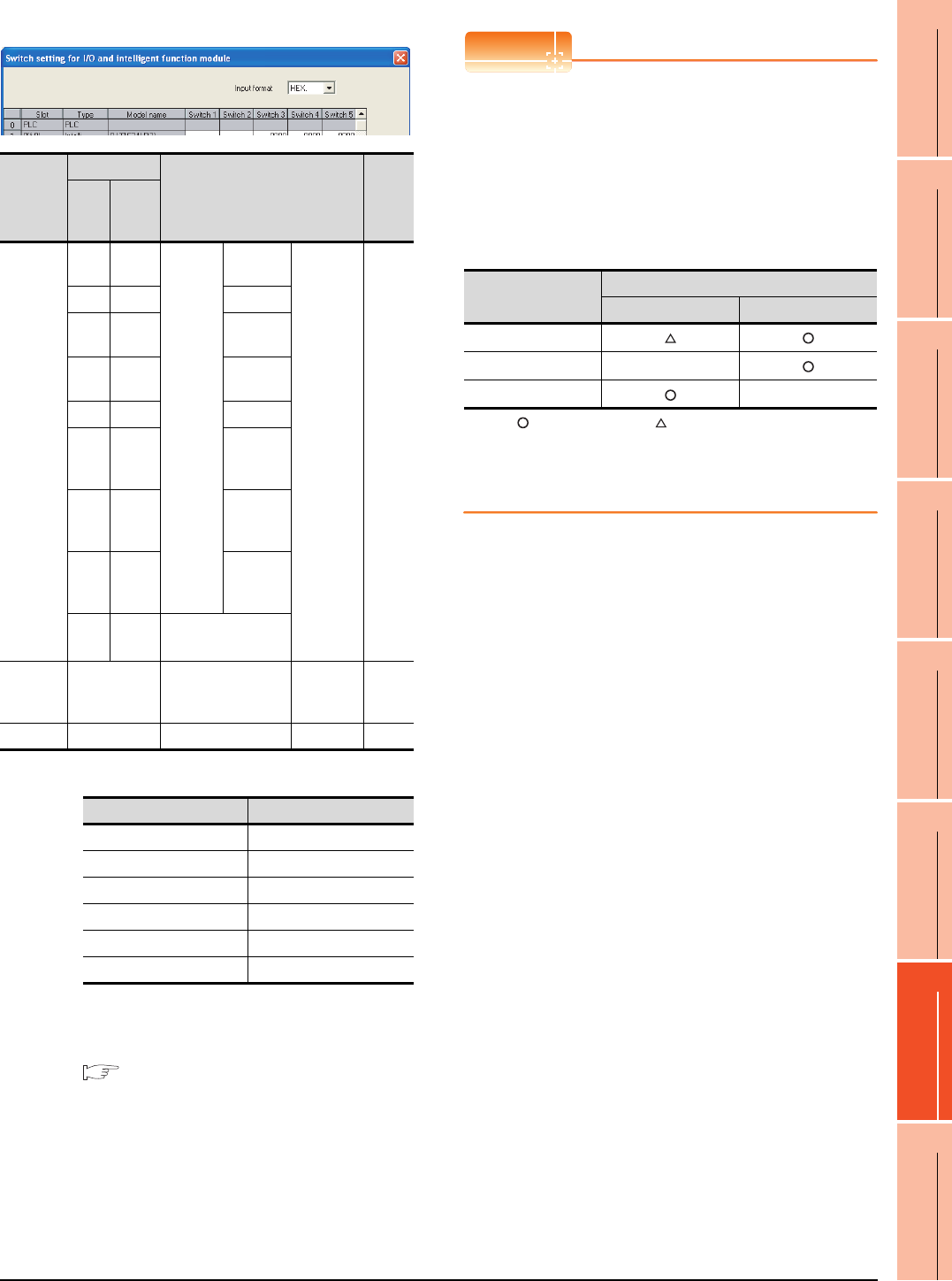
Transmission specifications Setting details
Operation setting Independent
Data bit 8bits
Parity bit Yes
Even/odd parity Odd
Stop bit 1bit
Sum check code Yes
Model
Connection of 2 GOTs
Function version A Function version B
QJ71C24(-R2)
QJ71C24N(-R2/R4) -
LJ71C24(-R2) -