


16. SERVO AMPLIFIER CONNECTION
16.6 Device Range that Can Be Set
16 - 27
9
MELSECNET/H
CONNECTION (PLC
TO PLC NETWORK)
10
MELSECNET/10
CONNECTION (PLC
TO PLC NETWORK)
11
CC-Link IE CONTROLLER
NETWORK
CONNECTION
12
CC-Link IE FIELD
NETWORK
CONNECTION
13
CC-Link CONNECTION
(INTELLIGENT DEVICE
STATION)
14
CC-Link
CONNECTION
(Via G4)
15
INVERTER
CONNECTION
16
SERVO AMPLIFIER
CONNECTION
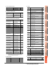
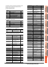
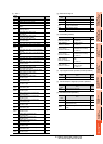
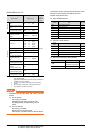
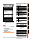
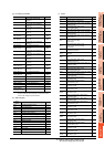
(f) Alarm (g) External I/O signal
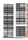
(h) Point table (position)
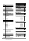
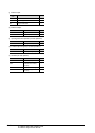
(i) Input signal for test operation (for test operation)
(j) Forced output of signal pin (for test operation)
(k) Set data (for test operation)
Device
name
Item Symbol
AL0 Current alarm number ―
AL1 Detailed data of current alarms ―
AL11 Servo status when alarm occurs current position ―
AL12
Servo status when alarm occurs command
position
―
AL13
Servo status when alarm occurs command
remaining distance
―
AL14
Servo status when alarm occurs
point table No.
―
AL15
Servo status when alarm occurs
cumulative feedback pulses
―
AL16
Servo status when alarm occurs
servo motor speed
―
AL17
Servo status when alarm occurs droop pulses
―
AL18 Servo status when alarm occurs override ―
AL19
Servo status when alarm occurs torque limit
voltage
―
AL20
Servo status when alarm occurs regenerative
load ratio
―
AL21
Servo status when alarm occurs effective load
ratio
―
AL22 Servo status when alarm occurs peak load ratio ―
AL23
Servo status when alarm occurs instantaneous
torque
―
AL24
Servo status when alarm occurs within one-
revolution position
―
AL25
Servo status when alarm occurs ABS counter
―
AL26
Servo status when alarm occurs
Load inertia moment ratio
―
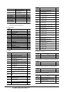
AL27 Servo status when alarm occurs bus voltage ―
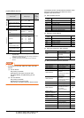
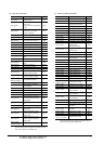
AL200
Alarm number from alarm history
most recent alarm
―
AL201
Alarm number from alarm history
first alarm in past
―
AL202
Alarm number from alarm history
second alarm in past
―
AL203
Alarm number from alarm history
third alarm in past
―
AL204
Alarm number from alarm history
fourth alarm in past
―
AL205
Alarm number from alarm history
fifth alarm in past
―
AL210
Alarm occurrence time in alarm history
most recent alarm
―
AL211
Alarm occurrence time in alarm history
first alarm in past
―
AL212
Alarm occurrence time in alarm history
second alarm in past
―
AL213
Alarm occurrence time in alarm history
third alarm in past
―
AL214
Alarm occurrence time in alarm history
fourth alarm in past
―
AL215
Alarm occurrence time in alarm history
fifth alarm in past
―
AL230
Detailed alarm from alarm history
most recent alarm
―
AL231
Detailed alarm from alarm history
first alarm in past
―
AL232
Detailed alarm from alarm history
second alarm in past
―
AL233
Detailed alarm from alarm history
third alarm in past
―
AL234
Detailed alarm from alarm history
fourth alarm in past
―
AL235
Detailed alarm from alarm history
fifth alarm in past
―
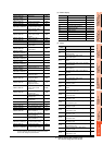
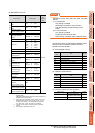
Device
name
Item Symbol
DI0 Input device statuses ―
DI1 External input pin statuses ―
DI2
Statuses of input devices switched on
through communication
―
DO0 Output device statuses ―
DO1 External output pin statuses ―
Device name Item Symbol
POS1 to POS31,
POS1001 to POS1031
Point table (position)
No. 1 to No. 31
―
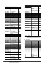
SPD1 to SPD31,
SPD1001 to SPD1031
Point table (speed)
No. 1 to No. 31
―
ACT1 to ACT31,
ACT1001 to ACT1031
Point table
(acceleration time constant)
No. 1 to No. 31
―
DCT1 to DCT31,
DCT1001 to DCT1031
Point table
(deceleration time constant)
No. 1 to No. 31
―
DWL1 to DWL31,
DWL1001 to DWL1031
Point table
(dwell)
No. 1 to No. 31
―
AUX1 to AUX31,
AUX1001 to AUX1031
Point table
(auxiliary function)
No. 1 to No. 31
―
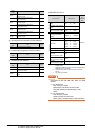
Device
name
Item Symbol
TMI0 Input signal for test operation ―
Device
name
Item Symbol
TMO0 Forced output of signal pin ―
Device
name
Item Symbol
TMD0 Writes the speed (test mode) ―
TMD1
Writes the acceleration/deceleration time
constant (test mode)
―
TMD2
Writes the moving distance in pulses (test
mode)
―