


14 - 8
14. CC-Link CONNECTION (Via G4)
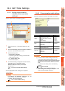
14.3 Connection Diagram
14.3 Connection Diagram
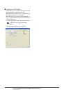
The following diagram shows the connection between the
GOT and the PLC.
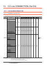
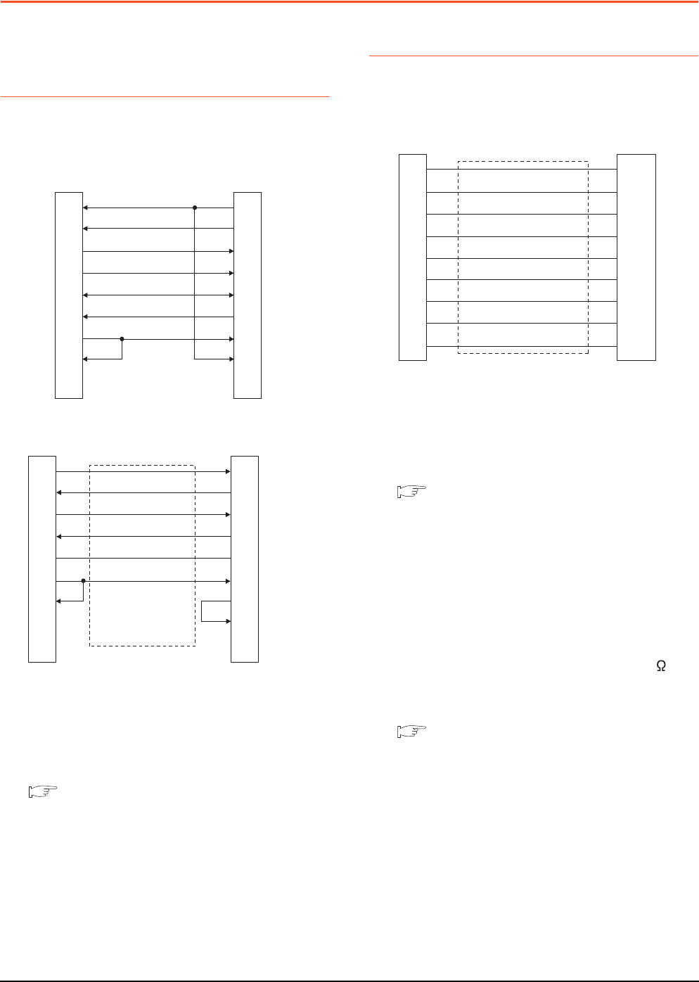
14.3.1 RS-232 cable
Connection diagram
Precautions when preparing a cable
(1) Cable length
The length of the RS-232 cable must be 15m or less.
(2) GOT side connector
For the GOT side connector, refer to the following.
1.4.1 GOT connector specifications
14.3.2 RS-422 cable
Connection diagram
Precautions when preparing a cable
(1) Cable length
The length of the RS-422 cable must be 500m or less.
(2) GOT side connector
For the GOT side connector, refer to the following.
1.4.1 GOT connector specifications
Connecting terminating resistors
(1) GOT side
When connecting a PLC to the GOT, a terminating
resistor must be connected to the GOT.
(a) For GT16, GT15, GT12
Set the terminating resistor setting switch of the
GOT main unit to "Disable".
(b) For GT14, GT11, GT10
Set the terminating resistor selector to "330 ".
For the procedure to set the terminating resistor, refer
to the following.
1.4.3 Terminating resistors of GOT
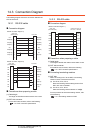
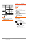
RS232 connection diagram 1)
RS232 connection diagram 2)
GOT side
(D-Sub 9-pin)
1
2
3
4
5
6
7
8
9
PLC side
7
3
2
6
5
4
1
8
9
CD
RD(RXD)
SD(TXD)
ER(DTR)
SG
DR(DSR)
RS(RTS)
CS(CTS)
-
RS(RTS)
SD(TXD)
RD(RXD)
DR(DSR)
SG
ER(DTR)
CD
CS(CTS)
-
GOT side
(terminal block)
PLC side
2
3
6
4
5
1
7
8
9
SD
RD
ER
DR
SG
RS
CS
NC
NC
RD(RXD)
SD(TXD)
DR(DSR)
ER(DTR)
SG
CD
RS(RTS)
CS(CTS)
NC
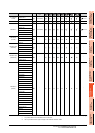
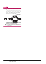
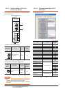
RS422 connection diagram 1)
GOT side
(terminal block)
Untied wire color of
GT10-C□□□R4-25P
Brown
Red
Orange
Yellow
Green
Blue
Purple
Black
White
SDA
SDB
RDA
RDB
SG
RSA
RSB
CSA
CSB