


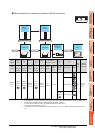
16. SERVO AMPLIFIER CONNECTION
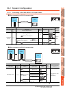
16.3 Connection Diagram
16 - 11
9
MELSECNET/H
CONNECTION (PLC
TO PLC NETWORK)
10
MELSECNET/10
CONNECTION (PLC
TO PLC NETWORK)
11
CC-Link IE CONTROLLER
NETWORK
CONNECTION
12
CC-Link IE FIELD
NETWORK
CONNECTION
13
CC-Link CONNECTION
(INTELLIGENT DEVICE
STATION)
14
CC-Link
CONNECTION
(Via G4)
15
INVERTER
CONNECTION
16
SERVO AMPLIFIER
CONNECTION
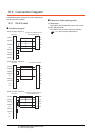
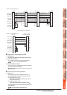
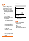
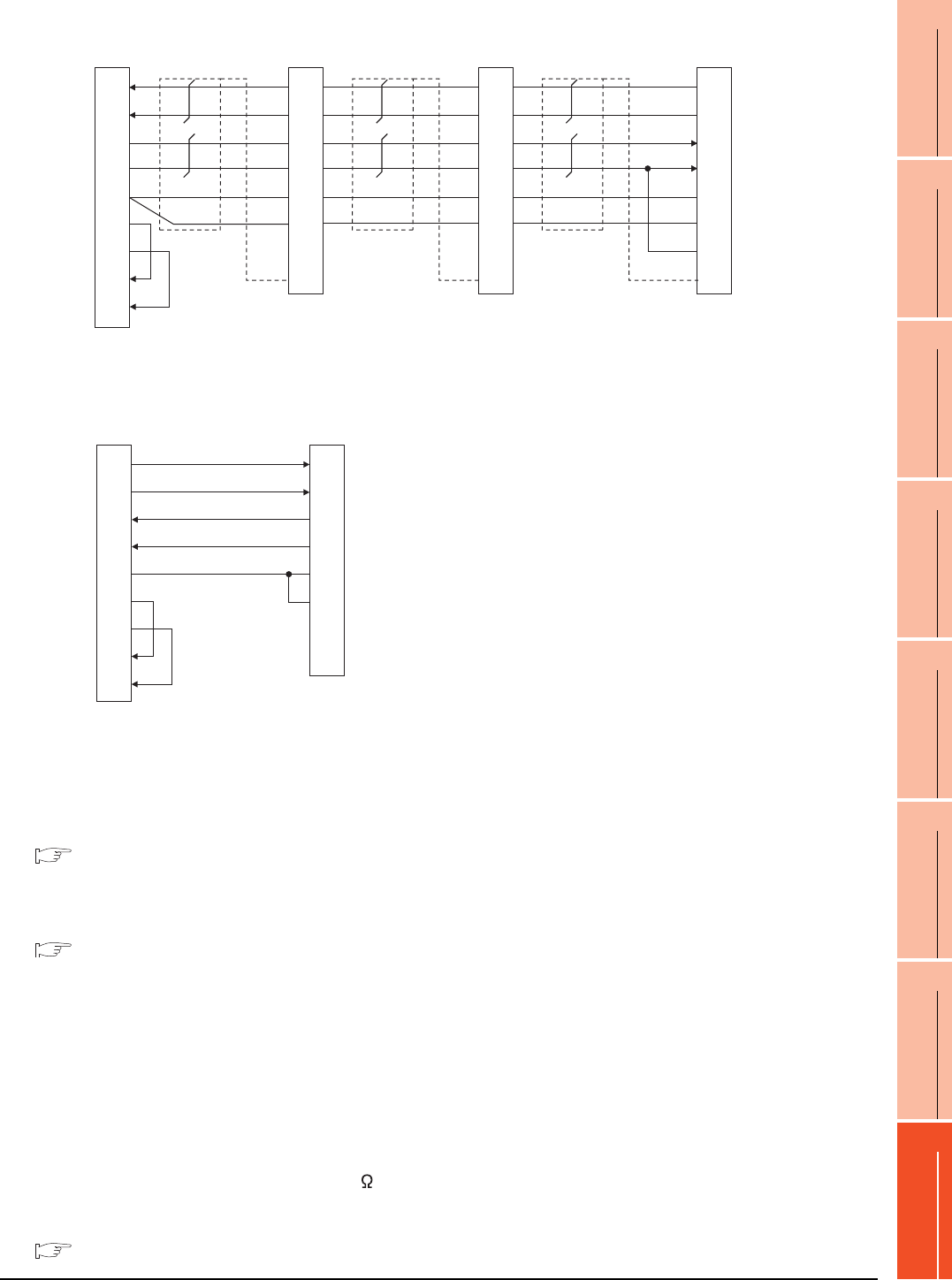
*1 At the last axis, connect TRE to RDN.
Precautions when preparing cable
(1) Cable length
The length of the RS-422 cable must be 30m or less.
(2) GOT side connector
For the GOT side connector, refer to the following.
1.4.1 GOT connector specifications
(3) Servo amplifier connector
Use the connector compatible with the servo amplifier.
For details, refer to the following.
See the technical data of the servo amplifier to
be used.
Connecting terminating resistors
(1) GOT side
When connecting a servo amplifier to the GOT, a
terminating resistor must be connected to the GOT.
(a) For GT16, GT15, GT12
Set the terminating resistor setting switch of the
GOT main unit to "No".
(b) For GT14, GT11, GT10
Set the terminating resistor selector to "330 ".
For the procedure to set the terminating resistor, refer
to the following.
1.4.3 Terminating resistors of GOT
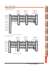
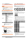
RS422 connection diagram 7)
GOT side Distributor Distributor
SDP
SDN
RDP
RDN
LG
LG
TRE
SDP
SDN
RDP
RDN
LG
LG
TRE
RXD+(RDA)
RXD-(RDB)
TXD+(SDA)
TXD-(SDB)
SG(GND)
RTS+(RSA)
RTS-(RSB)
CTS+(CSA)
CTS-(CSB)
3
4
1
2
5
6
7
8
9
9
19
5
15
11
1
10
Plate
9
19
5
15
11
1
10
Plate
Distributor
SDP
SDN
RDP
RDN
LG
LG
TRE
9
19
5
15
11
1
10
Plate
*
1
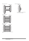
RS422 connection diagram 8)
1
2
3
4
5
6
7
8
9
GOT side
Distributor side
(Modular connector)
3
6
5
4
1
7
2
8
TXD+(SDA)
TXD-(SDB)
RXD+(RDA)
RXD-(RDB)
SG
RTS+(RSA)
RTS-(RSB)
CTS+(CSA)
CTS-(CSB)
RDP
RDN
SDP
SDN
LG
LG
P5D
NC