


15. INVERTER CONNECTION
15.3 Connection Diagram
15 - 23
9
MELSECNET/H
CONNECTION (PLC
TO PLC NETWORK)
10
MELSECNET/10
CONNECTION (PLC
TO PLC NETWORK)
11
CC-Link IE CONTROLLER
NETWORK
CONNECTION
12
CC-Link IE FIELD
NETWORK
CONNECTION
13
CC-Link CONNECTION
(INTELLIGENT DEVICE
STATION)
14
CC-Link
CONNECTION
(Via G4)
15
INVERTER
CONNECTION
16
SERVO AMPLIFIER
CONNECTION
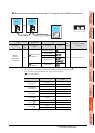
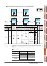
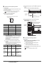
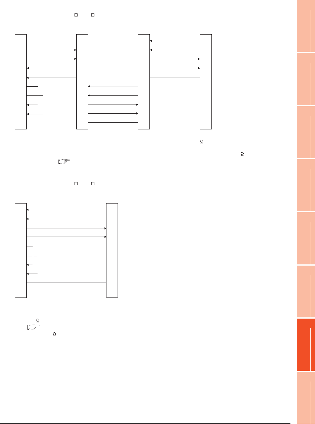
*1 Set the terminator switch built in the farthest inverter from the GOT to ON (100 ).
*2 For GT16, GT15 and GT12, set the terminating resistor of GOT side, which will be a terminal, to "Enable".
For GT14, GT11 and GT10, set the terminating resistor of GOT side, which will be a terminal, to "330 ".
1.4.3 Terminating resistors of GOT
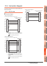
*1 For GT16, GT15 and GT12, set the terminating resistor to
"Disable".
For GT14, GT11 and GT10, set the terminating resistor to
"330 ".
1.4.3 Terminating resistors of GOT
*2 Turn ON (100 ) the terminator switch for the FR-E7TR.
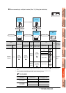
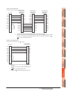
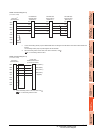
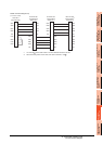
RS422 connection diagram 6)
(For GT16, GT15, GT14, GT12, GT11, GT105 , GT104 )
SG
SDB
SDA
RDB
RDA
RSA
RSB
CSA
CSB
SDA2
SDB2
RDA2
RDB2
GND
SDA1
SDB1
RDA1
RDB1
GND
GND
RDB1
RDA1
SDB1
SDA1
5
6
1
7
2
3
8
4
9
-
SDA2
SDB2
RDA2
RDB2
GND
SDA2
SDB2
RDA2
RDB2
GND
SDA1
SDB1
RDA1
RDB1
GND
GOT side
*
2
Built-in RS-485
terminal block
Station No.0
Built-in RS-485
terminal block
Station No.1
Built-in RS-485
terminal block
*
1
Station No.n
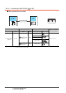
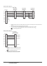
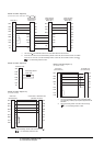
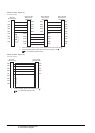
RS422 connection diagram 7)
(For GT16, GT15, GT14, GT12, GT11, GT105 , GT104 )
GOT side
*
1
RDA
RDB
SDA
SDB
RSA
RSB
CSA
CSB
SG
FG
2
7
1
6
3
8
4
9
5
-
SDA
SDB
RDA
RDB
SG
FR-E7TR side
(terminal block)
*
2