4 - 38
4. HOW TO MONITOR REDUNTANT SYSTEM
4.10 Switch the Monitor Target to the Control System Using the Script Function
4.10.2 Method for using the screen changing function
• As a feature of this function, monitor screens are created for each station number.
When the system switching occurs, the GOT can change the monitoring target to the control system PLC CPU on the
other monitor screen.
• To achieve this, the script of the GOT monitors the special relay SM1515 (Control system identification flag) of the
PLC CPU and stores the screen number corresponding to the latest station number of the control system into the
screen switching devices.
• Precautions:
There are the following 8 different screen switching devices.Set the screen switching devices for all screens to be
used.
(1) Base screen switching device
(2) Overlap window 1 switching device
(3) Overlap window 2 switching device
(4) Overlap window 3 switching device
(5) Overlap window 4 switching device
(6) Overlap window 5 switching device
(7) Superimpose window 1 switching device
(8) Superimpose window 2 switching device
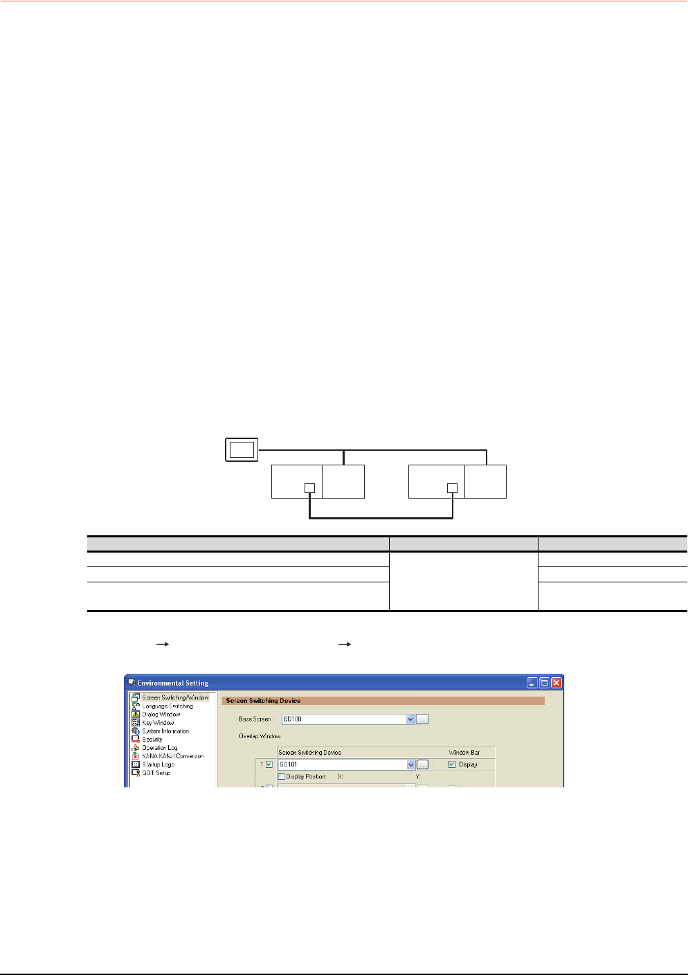
Setting method (For MELSECNET/H connection, MELSECNET/10 connection)
System configuration example 1: MELSECNET/H connection, MELSECNET/10 connection
1. Set the screen switching device of the base screen.
Select [Common] [GOT Environmental Setting] [Screen Switching/Window], and set the internal device
GD100 as the base screen switching device.
MELSECNET/H
(MELSECNET/H mode or MELSECNET/10 mode)
Network No. 1
GOT
Station No. 3
Control system
(System A)
Q25PRH
CPU
QJ71
BR11
Standby system
(System B)
Station No. 1
Q25PRH
CPU
QJ71
BR11
Station No. 2
Connected module Network No. Station No.
MELSECNET/H network module of control system
1
1
MELSECNET/H network module of standby system 2
GOT connected to MELSECNET/H network or MELSECNET/10
network
3


