


7. COMPUTER LINK CONNECTION
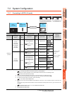
7.2 System Configuration
7 - 13
1
PREPARATORY
PROCEDURES FOR
MONITORING
2
DEVICE RANGE
THAT CAN BE SET
3
ACCESS RANGE
FOR MONITORING
4
HOW TO MONITOR
REDUNTANT
SYSTEM
5
BUS CONNECTION
6
DIRECT
CONNECTION TO
CPU
7
COMPUTER LINK
CONNECTION
8
ETHERNET
CONNECTION
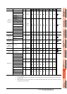
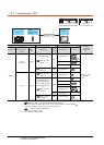
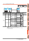
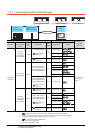
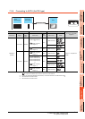
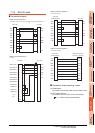
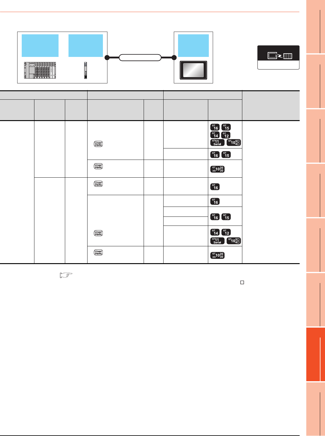
7.2.6 Connecting to ACPU (AnCPU type)
*1 For the system configuration on the computer link module side, refer to the following manual.
Computer Link Module (Com. link func./Print. func.) User’s Manual
*2 Connect it to the RS-232 interface (built into GOT). It cannot be mounted on GT1655 and GT155 .
*3 Use the RS-232 connection model.
*4 Use the RS-422 connection model.
Computer
link module
ACPU
(AnCPU type)
GOT
Connection cable
AJ71C24/UC24
Communication driver
PLC Connection cable GOT
Number of connectable
equipment
Model name
Computer link
module
*1
Commun
ication
type
Cable model
Max.
distance
Option device Model
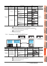
MELSEC-A
(AnCPU)
AJ71UC24 RS-232
GT09-C30R2-25P(3m)
or
RS232 connection
diagram 2)
15m
- (Built into GOT)
1 GOT for 1 computer link
module
GT15-RS2-9P
RS232 connection
diagram 4)
15m - (Built into GOT)
*3
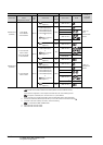
AJ71UC24 RS-422
RS422 connection
diagram 2)
500m - (Built into GOT)
GT09-C30R4-6C(3m)
GT09-C100R4-6C(10m)
GT09-C200R4-6C(20m)
GT09-C300R4-6C(30m)
or
RS422 connection
diagram 1)
500m
GT16-C02R4-9S
GT15-RS2T4-9P
*2
GT15-RS4-9S
- (Built into GOT)
RS422 connection
diagram 3)
500m - (Built into GOT)
*4