


3. ACCESS RANGE FOR MONITORING
3.1 Access Range for Monitoring Stations on Network Systems
3 - 5
1
PREPARATORY
PROCEDURES FOR
MONITORING
2
DEVICE RANGE
THAT CAN BE SET
3
ACCESS RANGE
FOR MONITORING
4
HOW TO MONITOR
REDUNTANT
SYSTEM
5
BUS CONNECTION
6
DIRECT
CONNECTION TO
CPU
7
COMPUTER LINK
CONNECTION
8
ETHERNET
CONNECTION
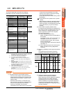
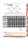
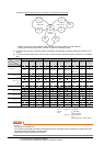
MELSECNET/H connection, MELSECNET/10 connection, CC-Link IE Controller Network
connection, CC-Link IE Field Network connection
POINTPOINTPOINT
Precautions for cyclic transmission
When transmitting cyclic transmission with a GOT, even if link device X and/or Y are assigned to a GOT when
setting the network parameter for the control station, the GOT cannot access the host station.
When transmitting cyclic transmission, use link device B and/or W.
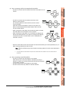
• The GOT is regarded as a normal station and monitors the control station and all normal stations on the
network.
When the monitoring target is a PLC CPU within a multiple CPU system, the GOT can monitor CPU No. 1 to
CPU No. 4 by specifying CPU No.
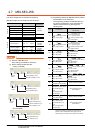
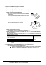
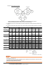
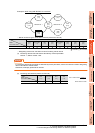
• When monitoring other networks, a CPU on another Ethernet, MELSECNET/H, MELSECNET/10, CC-Link IE
Controller Network, or CC-Link field network is accessible via the PLC CPU.
However, the GOT cannot monitor the CNC C70 on other networks.
On the Ethernet network, only QCPU (Q mode) and QnACPU can be accessed.
• When monitoring other networks in MELSECNET/10 connection, install the MELSECNET/H communication
unit on the GOT.
• To monitor other networks, setting of routing parameters is required.
For routing parameter setting, refer to the following manuals.
Routing parameter setting for the GOT
9. MELSECNET/H CONNECTION (PLC TO PLC NETWORK)
10. MELSECNET/10 CONNECTION (PLC TO PLC NETWORK)
11. CC-Link IE CONTROLLER NETWORK CONNECTION
12. CC-Link IE FIELD NETWORK CONNECTION
Routing parameter setting for the PLC CPU (MELSECNET/H network system, MELSECNET/10 network
system)
Q Corresponding MELSECNET/H Network System Reference Manual (PLC to PLC network)
Routing parameter setting for the PLC CPU (When connecting to the CC-Link IE Controller Network)
CC-Link IE Controller Network Reference Manual
Routing parameter setting for the PLC CPU (When connecting to the CC-Link IE Field Network)
CC-Link IE Field Network Master/Local Module User's Manual
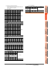
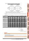
• If devices of other stations (other than devices B and W that are allocated by the network parameter) are
monitored, monitoring may not be available depending on the PLC CPU of the network system to be monitored.
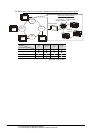
■ Monitor accessible range of other stations and setting method of monitor devices Example 5:
When using MELSECNET/10 connection