


16 - 42
16. SERVO AMPLIFIER CONNECTION
16.6 Device Range that Can Be Set
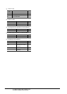
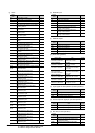
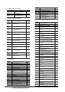
(h) Extension setting 2 parameter
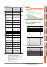
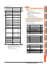
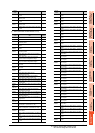
(i) Extension setting 3 parameter
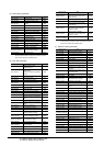
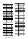
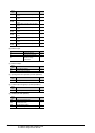
(j) Status display
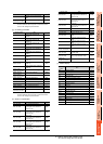
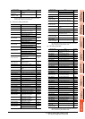
(k) Alarm (compatible with MELSERVO-J3-*A)
Device name Item Symbol
PE1 to 40,
PE1000 to 1040
For manufacturer setting ―
PE41, PE1041 Function selection E-3 EOP3
PE42 to 64,
PE1042 to 1064
For manufacturer setting ―
Device
name
Item Symbol
PF1 to 8,
PF1001 to
1008
For manufacturer setting ―
PF9,
PF1009
Function selection F-5 *FOP5
PF10 to 14,
PF1010 to
1014
For manufacturer setting ―
PF15,
PF1015
Electronic dynamic brake operating time DBT
PF16 to 20,
PF1016 to
1020
For manufacturer setting ―
PF21,
PF1021
Drive recorder switching time setting DRT
PF22,
PF1022
For manufacturer setting ―
PF23,
PF1023
Vibration tough drive - Oscillation detection
level
OSCL1
PF24,
PF1024
Vibration tough drive function selection OSCL2
PF25,
PF1025
Instantaneous power failure tough drive
- Detection time
CVAT
PF26 to 30,
PF1026 to
1030
For manufacturer setting ―
PF31,
PF1031
Machine diagnosis function - Friction
judgement speed
FRIC
PF32 to 48,
PF1032 to
1048
For manufacturer setting ―
Device
name
Item Symbol
ST0 Comulative feedback pulse ―
ST1 Servo motor speed ―
ST2
Droop pulse
―
ST3 Cumulative command pulse ―
ST4 Command pulse frequency ―
ST5 Analog speed command voltage/limit voltage ―
ST6
Analog torque command voltage/limit
voltage
―
ST7 Regenerative load ratio ―
ST8
Effetive load ratio
―
ST9 Peak load ratio ―
ST10 Instantaneous torque ―
ST11 Within one-revolution position(1 pulse unit) ―
ST12 ABS counter ―
ST13 Load inertia moment ratio ―
ST14
Bus voltage
―
ST15 to 31 For manufacturer setting ―
ST32 Internal temperature of encoder ―
ST33
Setting time
―
ST34 Oscillation detection frequency ―
ST35 Number of tough drives ―
ST36 to 39 For manufacturer setting ―
ST40
Unit power consumption 1
(incremwnt of 1 W)
―
ST41
Unit total power consumption 1
(incremwnt of 1 Wh)
―
Device
name
Item Symbol
AL0 Current alarm number ―
AL1 Detailed data of current alarms ―
AL11
Servo status when alarm occurs Cumulative
feedback pulses
―
AL12
Servo status when alarm occurs Servo motor
speed
―
AL13
Servo status when alarm occurs Droop
pulses
―
AL14
Servo status when alarm occurs cumulative
command pulses
―
AL15
Servo status when alarm occurs command
pulse frequency
―
AL16
Servo status when alarm occurs analog
speed command voltage/limit voltage
―
AL17
Servo status when alarm occurs analog
torque command voltage/limit voltage
―
AL18
Servo status when alarm occurs regenerative
load ratio
―
AL19
Servo status when alarm occurs effective
load ratio
―
AL20
Servo status when alarm occurs peak load
ratio
―
AL21
Servo status when alarm occurs
Instantaneous torque
―
AL22
Servo states when alarm occurs Within
onerevolution position(1 pulse unit)
―
AL23 Servo status when alarm occurs ABS counter ―
AL24
Servo status when alarm occurs load inertia
moment ratio
―
AL25 Servo status when alarm occurs Bus voltage ―
AL200
Alarm number from Alarm History most
recent alarm
―
AL201
Alarm number from Alarm History first alarm
in past
―
AL202
Alarm number from Alarm History second
alarm in past
―
AL203
Alarm number from Alarm History third alarm
in past
―
AL204
Alarm number from Alarm History fourth
alarm in past
―
AL205
Alarm number from Alarm History fifth alarm
in past
―
AL210
Alarm occurrence time in alarm history most
recent alarm
―
AL211
Alarm occurrence time in alarm history first
alarm in past
―
AL212
Alarm occurrence time in alarm history
second alarm in past
―
AL213
Alarm occurrence time in alarm history third
alarm in past
―
AL214
Alar
m occurrence time in alarm history fourth
alarm in past
―
AL215
Alarm occurrence time in alarm history fifth
alarm in past
―
AL230
Detailed alarm from Alarm History most
recent alarm
―
Device
name
Item Symbol