


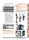


8. ETHERNET CONNECTION
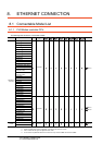
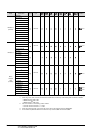
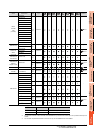
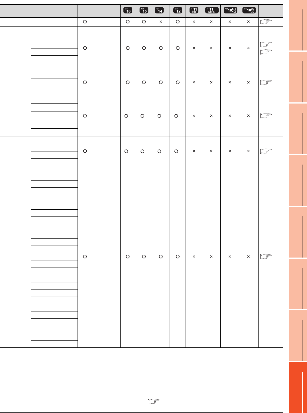
8.1 Connectable Model List
8 - 3
1
PREPARATORY
PROCEDURES FOR
MONITORING
2
DEVICE RANGE
THAT CAN BE SET
3
ACCESS RANGE
FOR MONITORING
4
HOW TO MONITOR
REDUNTANT
SYSTEM
5
BUS CONNECTION
6
DIRECT
CONNECTION TO
CPU
7
COMPUTER LINK
CONNECTION
8
ETHERNET
CONNECTION
(Continued to next page)
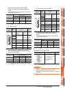
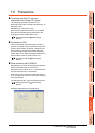
*1 If the A series Ethernet module is applied to the QnACPU, the GOT can monitor the devices as the same as the case of AnACPU.
However, the following devices cannot be monitored.
• Devices added to QnACPU
• Latch relays (L) and step relays (S)
(In case of QnACPU, the latch relay (L) and step relay (S) are different from the internal relay. However, whichever is specified,
an access is made to the internal relay.)
• File register (R)
*2 GT14 models compatible with Ethernet connection are only GT1455-QTBDE and GT1450-QLBDE.
*3 Combination with the Ethernet module is restricted. 8.1.2 Ethernet module
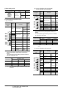
Series Model name Clock
Communication
type
*2
Refer to
MELSEC-QS QS001CPU Ethernet
8.2.1
MELSEC-L
L02CPU
Ethernet
8.2.2
8.2.1
L26CPU
L26CPU-BT
L02CPU-P
L26CPU-PBT
L02SCPU
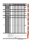
MELSEC-Q
(A mode)
Q02CPU-A
*3
Ethernet
8.2.1
Q02HCPU-A
*3
Q06HCPU-A
*3
MELSEC-QnA
(QnACPU)
Q2ACPU
*3
Ethernet
*1 *1 *1 *1
8.2.1
Q2ACPU-S1
*3
Q3ACPU
*3
Q4ACPU
*3
Q4ARCPU
*3
MELSEC-QnA
(QnASCPU)
Q2ASCPU
Ethernet
*1 *1 *1 *1
8.2.1
Q2ASCPU-S1
Q2ASHCPU
Q2ASHCPU-S1
MELSEC-A
(AnCPU)
A2UCPU
Ethernet
8.2.1
A2UCPU-S1
A3UCPU
A4UCPU
A2ACPU
A2ACPUP21
A2ACPUR21
A2ACPU-S1
A2ACPUP21-S1
A2ACPUR21-S1
A3ACPU
A3ACPUP21
A3ACPUR21
A1NCPU
A1NCPUP21
A1NCPUR21
A2NCPU
A2NCPUP21
A2NCPUR21
A2NCPU-S1
A2NCPUP21-S1
A2NCPUR21-S1
A3NCPU
A3NCPUP21
A3NCPUR21