


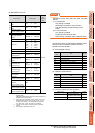
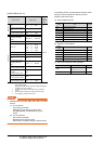
16. SERVO AMPLIFIER CONNECTION
16.6 Device Range that Can Be Set
16 - 31
9
MELSECNET/H
CONNECTION (PLC
TO PLC NETWORK)
10
MELSECNET/10
CONNECTION (PLC
TO PLC NETWORK)
11
CC-Link IE CONTROLLER
NETWORK
CONNECTION
12
CC-Link IE FIELD
NETWORK
CONNECTION
13
CC-Link CONNECTION
(INTELLIGENT DEVICE
STATION)
14
CC-Link
CONNECTION
(Via G4)
15
INVERTER
CONNECTION
16
SERVO AMPLIFIER
CONNECTION
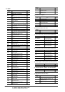
(7) MELSERVO-J3-*A
*1 1 to 50 of PA, PB, PC, and PD are used when writing data to
the servo amplifier RAM.
1001 to 1050 of PA, PB, PC, and PD are used when writing
data to E
2
PROM of the servo amplifier.
*2 The GOT cannot read or write data from/to consecutive
devices.
*3 Only reading is possible.
*4 Only reading is possible for DI0 to DI1.
POINTPOINTPOINT
Precautions for SP, OM, TMB, TMI, TMO, and TMD
devices
(1) For bit devices
Only writing is possible.
[Alternate] of a bit switch cannot be used.
Use [Set], [Reset], and [Momentary] of a bit
switch.
(2) For word devices
Only writing is possible.
Numerical input cannot be used.
When writing, use [Word Set] of a data set switch.
The following shows correspondences between virtual
devices for servo amplifier and data of the servo
amplifier used with the GOT.
(a) Servo amplifier request
(b) Operation mode selection
(c) Instruction demand (for test operation)
(d) Basic parameter/expansion parameter
*1 For the parameters prefixed by an asterisk (*), setting
becomes effective when the power is turned off once and
back on after setting the parameter data.
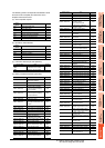
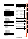
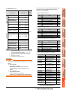
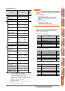
Device name
*2
Setting range
Device
No.
represen
tation
Bit device
Servo amplifier request (SP) SP0 to SP6
Decimal
Operation mode selection
(OM)
OM0 to OM4
Instruction demand
(for test operation) (TMB)
TMB1 to TMB6
Word device
Basic setting parameter
(PA)
*1
PA1 to PA19
PA1001 to PA1019
Gain filter parameter
(PB)
*1
PB1 to PB45
PB1001 to PB1045
Extension setting parameter
(PC)
*1
PC1 to PC50
PC1001 to PC1050
I/O setting parameter (PD)
*1
PD1 to PD30
PD1001 to PD1030
Status display (ST)
*3
ST0 to ST14
Alarm (AL)
*3
AL0 to AL1
AL11 to AL25
AL200 to AL205
AL210 to AL215
AL230 to AL235
External input (DI)
*4
DI0 to DI2
External output (DO)
*3
DO0 to DO1
Input signal for test operation
(for test operation) (TMI)
TMI0
Forced output of signal pin
(for test operation) (TMO)
TMO0
Set data
(for test operation) (TMD)
TMD0 to TMD1
TMD3
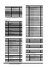
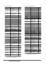
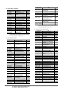
Device
name
Item Symbol
SP0 Status display data clear ―
SP1 Current alarm clear ―
SP2 Alarm history clear ―
SP3 External input signal prohibited ―
SP4 External output signal prohibited ―
SP5 External input signal resumed ―
SP6 External output signal resumed ―
Device
name
Item Symbol
OM0 Normal mode (not test operation mode) ―
OM1 JOG operation ―
OM2 Positioning operation ―
OM3 Motorless operation ―
OM4 Output signal (DO) forced output ―
Device
name
Item Symbol
TMB1 Temporary stop command ―
TMB2
Test operation (positioning operation) start
command
―
TMB3 Forward rotation direction ―
TMB4 Reverse rotation direction ―
TMB5 Restart for remaining distance ―
TMB6 Remaining distance clear ―
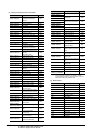
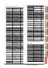
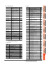
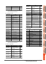
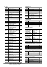
Device name Item
Symbol
*1
PA1, PA1001 Control mode *STY
PA2, PA1002 Regenerative brake option *REG
PA3, PA1003
Absolute position detection
system
*ABS
PA4, PA1004 Function selection A-1 *AOP1
PA5, PA1005
Number of command input
pulses per revolution
*FBP
PA6, PA1006
Electronic gear numerator
(command pulse multiplying
factor numerator)
CMX
PA7, PA1007
Electronic gear denominator
(command pulse multiplying
factor denominator)
CDV
PA8, PA1008 Auto tuning mode ATU
PA9, PA1009 Auto tuning response RSP
PA10, PA1010 In-position range INP
PA11, PA1011 Forward torque limit TLP
PA12, PA1012 Reverses torque limit TLN
PA13, PA1013 Command pulse input form *PLSS
PA14, PA1014 Rotation direction selection *POL
PA15, PA1015 Encoder output pulses *ENR
PA16 to PA18,
PA1016 to PA1018
For manufacturer setting ―
PA19, PA1019 Parameter block *BLK