8. ETHERNET CONNECTION
8.4 PLC Side Setting
8 - 39
1
PREPARATORY
PROCEDURES FOR
MONITORING
2
DEVICE RANGE
THAT CAN BE SET
3
ACCESS RANGE
FOR MONITORING
4
HOW TO MONITOR
REDUNTANT
SYSTEM
5
BUS CONNECTION
6
DIRECT
CONNECTION TO
CPU
7
COMPUTER LINK
CONNECTION
8
ETHERNET
CONNECTION
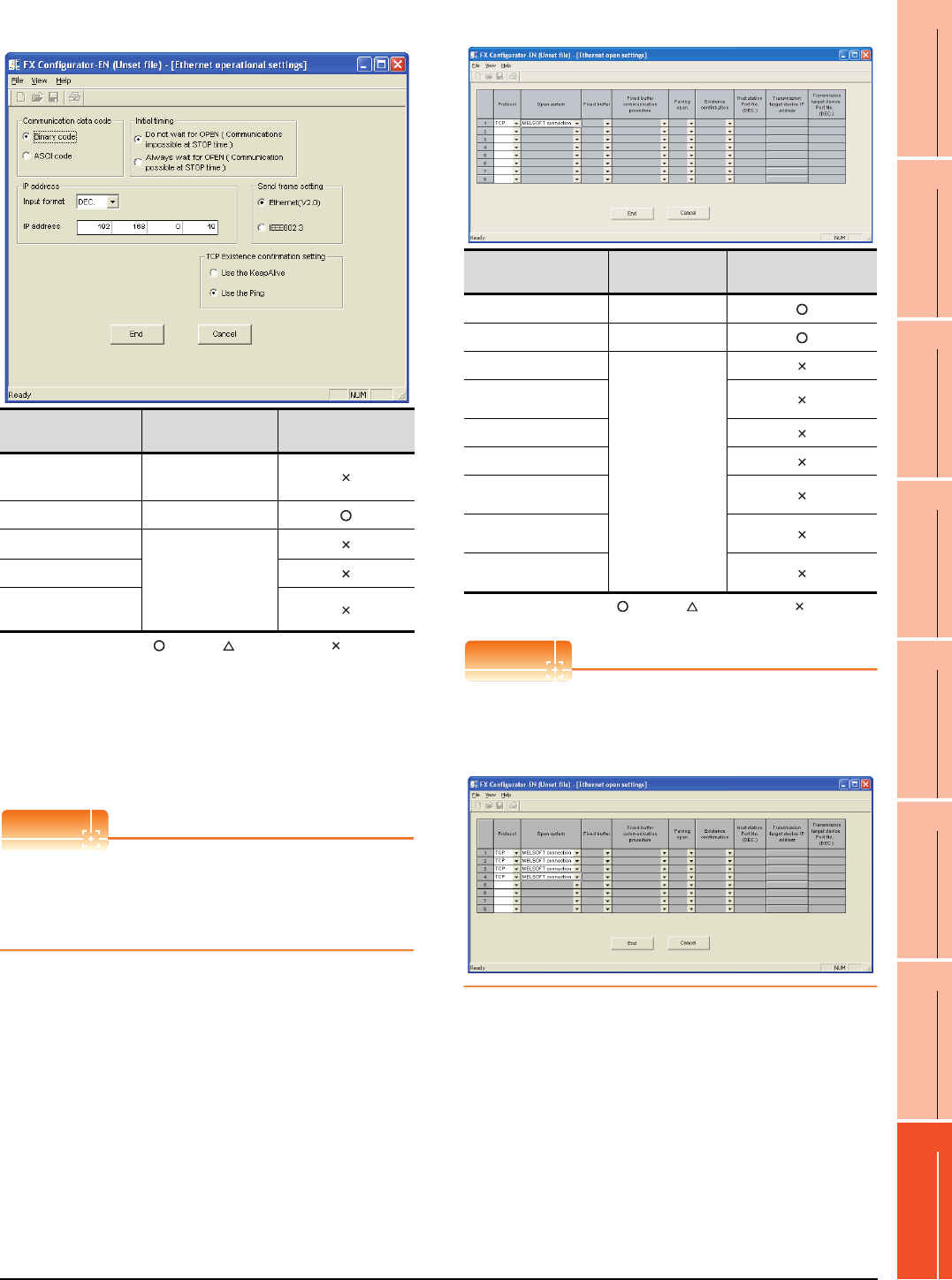
(2) Operational settings
:Required :Set if necessary :Not required
*1
Because the port No. 5551 is fixed, the GOT oper-
ates as follows, regardless of the setting for the item.
• Communication date code : [Binary code]
• Initial timing : [Always wait for OPEN]
(Communications are enabled while the programmable
controller CPU stops.)
*2 The default value of IP address is 192.168.1.254. Set the IP
address corresponding to the system configuration.
POINTPOINTPOINT
When changing Ethernet parameter
After writing the Ethernet parameter to the
programmable controller CPU, turn off and then on, or
reset the programmable controller CPU.
(3) Open settings
:Required :Set if necessary :Not required
POINTPOINTPOINT
When connecting to multiple GOTs and peripheral
devices
The number of protocols equivalent to that of the GOTs
and devices must be set.
Item Setting
Setting
(with GOT connected)
Communication
date code
*1
(Use default value.)
IP address 192.168.0.19
Initial timing
*1
(Use default value.)
Send frame setting
TCP Existence
confirmation setting
Item Setting
Setting
(with GOT connected)
Protocol TCP
Open system MELSOFT connection
Fixed buffer
(Use default value.)
Fixed buffer communication
procedure
Pairing open
Existence confirmation
Host station Port No.
(DEC.)
Transmission target device
IP address
Transmission target device
Port No. (DEC.)


