


15 - 28
15. INVERTER CONNECTION
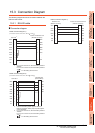
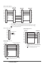
15.3 Connection Diagram
Precautions when preparing a cable
(1) Cable length
The length of the RS-422 cable must be 500m or less.
(2) GOT side connector
For the GOT side connector, refer to the following.
1.4.1 GOT connector specifications
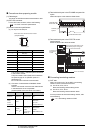
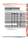
(3) Inverter connector specifications
(a) Pin layout in the PU port
The contents inside ( ) indicate symbols described
in the inverter manual.
The pins number 2 and 8 (P5S) are connected to
the power supply for an operation panel or a
parameter unit.
Do not use them in RS-422 communication.
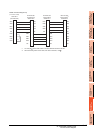
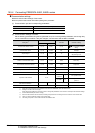
(b) Connector of cable between FREQROL Series
inverters
Use the commercial connectors and cables shown
in the table below or the comparable
products.(Refer to the manual for the inverter.)
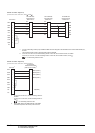
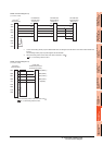
(4) Terminal block layout in the FR-A5NR computer link
option
Attach this option to the A500 and F500 Series.
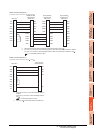
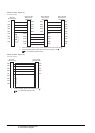
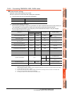
(5) Terminal block layout in the FR-E7TR control
terminal option
Mount the FR-E7TR to the E700 series.
Connecting terminating resistors
(1) GOT side
When connecting a PLC to the GOT, a terminating
resistor must be connected to the GOT.
(a) For GT16, GT15, GT12
Set the terminating resistor setting switch.
(b) For GT14, GT11, GT10
Set the terminating resistor selector switch.
For the procedure to set the terminating resistor, refer
to the following.
1.4.3 Terminating resistors of GOT
Pin No. Signal name Remark
1GND (SG)
2 (P5S) Not used
3RXD+ (RDA)
4TXD- (SDB)
5TXD+ (SDA)
6 RXD- (RDB)
7GND (SG)
8 (P5S) Not used
Name Model name Specifications Manufacturer
Connector 5-554720-3 RJ45 connector
Tyco International,
Ltd
Modular
ceiling
rosette
(Distributor)
BMJ-8 -
HACHIKO
ELECTRIC
CO.,LTD.
TEL(03)-3806-9171
Cable
SGLPEV
0.5mm 4P
Cable
conforming to
EIA568
(such as cable
10BASE-T)
MITSUBISHI
CABLE
INDUSTRIES, LTD.
When seen from the front of the inverte
r
(receptacle side)
Modular jack
SDBSDA RDA RDB RDR SG
A
B
C
Connected to the GOT
Terminal block
Screw size: M3
Terminal
symbol
O
N
OPENOPEN
100100
SOURCESOURCE
SINKSINK
V
II
SE
SDA SDB RDA RDB SG 2
SDA
SDB RDA
RDB
SG
2
SDA SDBRDA RDB RUN FU
SDA
SDB RDA RDB
RUN
FU
SE
10
4
RM
RH
MRS
RES
SD
PC
STF
STR
SD SD
A
B
C
FM
RL
To the GOT or
the previous
inverter
Set the terminal 2/SG switch to the
right position (ON) to change the
terminal 2 to the terminal SG.
To the next inverter