


4. HOW TO MONITOR REDUNTANT SYSTEM
4.10 Switch the Monitor Target to the Control System Using the Script Function
4 - 41
1
PREPARATORY
PROCEDURES FOR
MONITORING
2
DEVICE RANGE
THAT CAN BE SET
3
ACCESS RANGE
FOR MONITORING
4
HOW TO MONITOR
REDUNTANT
SYSTEM
5
BUS CONNECTION
6
DIRECT
CONNECTION TO
CPU
7
COMPUTER LINK
CONNECTION
8
ETHERNET
CONNECTION
Setting method (Ethernet connection)
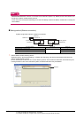
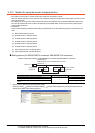
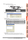
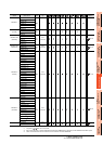
System configuration example 2: Ethernet connection
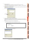
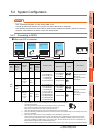
1. Set the screen switching device of the base screen.
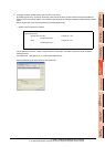
Select [Common] [GOT Environmental Setting] [Screen Switching/Window], and set the internal device
GD100 as the base screen switching device.
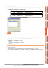
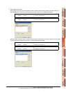
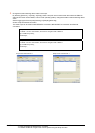
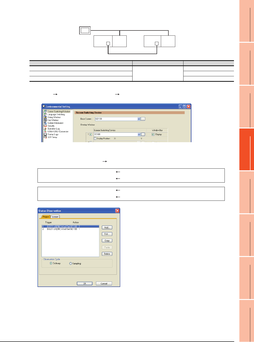
2. Set the status observation.
Make the setting so that the station number is switched when the faulty station information (GS231) from the station
monitoring specified by selecting [Common] [Status Observation] turns ON.
3. Set monitor screens.
For MELSECNET/H connection, MELSECNET/10 connection or Ethernet connection: (Common)
• Create a monitor screen with each object whose network setting is Station No. 1 on Screen No. 1 (1-1).
• Create a monitor screen with each object whose network setting is Station No. 2 on Screen No. 2 (1-2).
Ethernet
Network No. 1
GOT
Station No. 3
Control system
(System A)
Q25PRH
CPU
QJ71
E71
Standby system
(System B)
Station No. 1
Q25PRH
CPU
QJ71
E71
Station No. 2
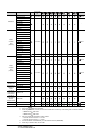
Connected module Network No. Station No.
Ethernet module of control system
1
1
Ethernet module of standby system 2
GOT connected to the Ethernet network 3
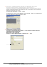
Condition 1 : GS231.b0 (while ON) When b0 is ON, Station No. 1 is abnormal.
Operation : GD100=2 Screen No. is changed to 2.
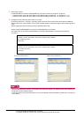
Condition 1 : GS231.b1 (while ON) When b1 is ON, Station No. 2 is abnormal.
Operation : GD100=1 Screen No. is changed to 1.