


2. DEVICE RANGE THAT CAN BE SET
2.6 MELSEC-FX
2 - 13
1
PREPARATORY
PROCEDURES FOR
MONITORING
2
DEVICE RANGE
THAT CAN BE SET
3
ACCESS RANGE
FOR MONITORING
4
HOW TO MONITOR
REDUNTANT
SYSTEM
5
BUS CONNECTION
6
DIRECT
CONNECTION TO
CPU
7
COMPUTER LINK
CONNECTION
8
ETHERNET
CONNECTION
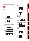
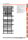
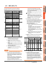
2.6 MELSEC-FX
The device ranges that can be set when selecting
[MELSEC-FX] as the controller type are as follows.
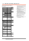
*1 When executing the touch switch function set during the bit
specification of the word device, do not write any data to the
word device through the sequence program.
*2 The device No. must be set in multiples of 16.
*3 Only 16-bit (1-word) designation is allowed.
*4 For CS0 to CS199, only 16-bit (1-word) designation is
allowed.
For CS200 to CS255, only 32-bit (2-word) designation is
allowed.
*5 Monitoring or writing is not possible in the continuous device
designation mode.
In addition, setting values of the timer and counter, which are
not used for the program, cannot be monitored. If monitoring
is executed, a reading error occurs.
*6 This is not supported by GT10.
*7 Can be used only for special blocks or special units
compatible with FX
1N, FX1NC, FX2N, FX2NC, FX3G, FX3GC,
FX
3U, FX3UC.
(Except FX
0N-3A, FX2N-2AD, and FX2N-2DA)
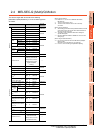
POINTPOINTPOINT
(1) Precautions when using the buffer memory
• When the power supply of the special block or
special module is turned off, the contents of the
buffer memory are initialized, except for some
keeping areas.
• When the buffer memory is monitored by the
GOT, the PLC scan time may increase instantly.
• Use the 16 bit specification for the buffer
memory of 16 bit data. Use the 32 bit
specification for the buffer memory of 32 bit data.
If using the 16 bit specification for a buffer
memory of 32 bit data, monitoring and writing
may not be executed normally.
For the data size of each buffer memory, refer to
the following.
User's Manual of the special block or special
module
• When reading from/writing to the special block or
special module by interrupt processing of the
sequence program, monitoring/writing from GOT
to the buffer memory may not be executed
normally.
(2) How to select a keyword protection level
For equipment that are allowed to operate the FX
PLC online, 3 levels of protection level can be set.
When monitoring or changing settings by any
online equipment is required, set a keyword
referring to the following.
(a) When setting the keyword only
Select a protection level by the initial letter of
the keyword.
All operation protect: Set a keyword with the
initial letter "A", "D" to "F", or "0" to "9".
Incorrect write/read protect: Set a keyword
with the initial letter "B".
Incorrect write protect: Set a keyword with the
initial letter "C".
(b) When setting the keyword and 2nd keyword
Select a protection level by [Registration
condition].
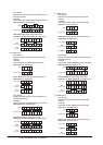
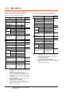
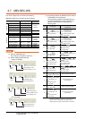
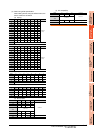
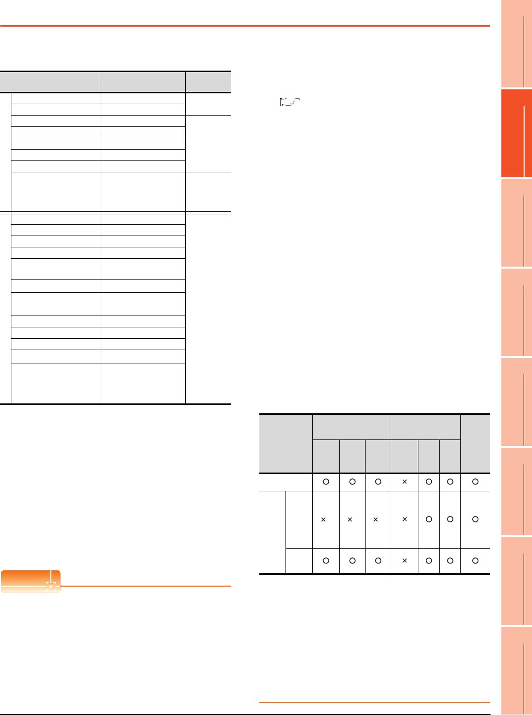
(3) Monitoring availability at each keyword protection
level
The following shows the device monitoring
availability at each keyword protection level.
*1 When the T, C set values are specified indirectly, changing
devices is available.
(4) Difference between all online operations
prohibition and all operations prohibition
When specifying all online operations prohibition,
displaying devices and inputting data with
programming tools or GOT are all prohibited.
When all operations are prohibited, displaying
devices and inputting data with the GOT are
enabled while all operations using programming
tools are prohibited.
Device name Setting range
Device No.
representation
Bit device
Input relay (X) X0 to X377
Octal
Output relay (Y) Y0 to Y377
Auxiliary relay (M) M0 to M7679
Decimal
Special auxiliary relay (M) M8000 to M8511
State (S) S0 to S4095
Timer contact (T) T0 to T511
Counter contact (C) C0 to C255
Word device bit
*1
Specified bit of the
following word devices
(Except Timer (set value)
and Counter (set value))
―
Word device
Data register (D) D0 to D0999
Decimal
File register (D) D1000 to D7999
Special data register (D) D8000 to D8511
Timer (current value) (T) T0 to T511
Counter (current value)
(C)
C0 to C255
Timer (set value) (TS)
*3*5
TS0 to TS511
Counter (set value)
(CS)
*4*5
CS0 to CS255
Extension register (R) R0 to
R32767
Index register (V) V0 to V7
Index register (Z) Z0 to Z7
Buffer memory (BM)
*7
BM0 to
BM32767
Bit device word
*2*6
Converting the above bit
devices into words
(Except Timer contact
and Counter contact)
Item
When registering the
keyword only
When registering the
keyword and 2nd
keyword
Keyword
not
registered
or
protection
cancelled
All
operation
protect
Incorrect
write/
read
protect
Incorrect
write
protect
All online
operation
protect
Read/
write
protect
Write
protect
Monitoring
devices
Changing
devices
T, C set
value
and file
register
(D1000
and the
following)
*1 *1 *1
Other
than
above