


19 - 26
19. GOT MULTI-DROP CONNECTION
19.6 Setting of Serial Multi-Drop Connection Unit
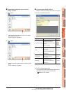
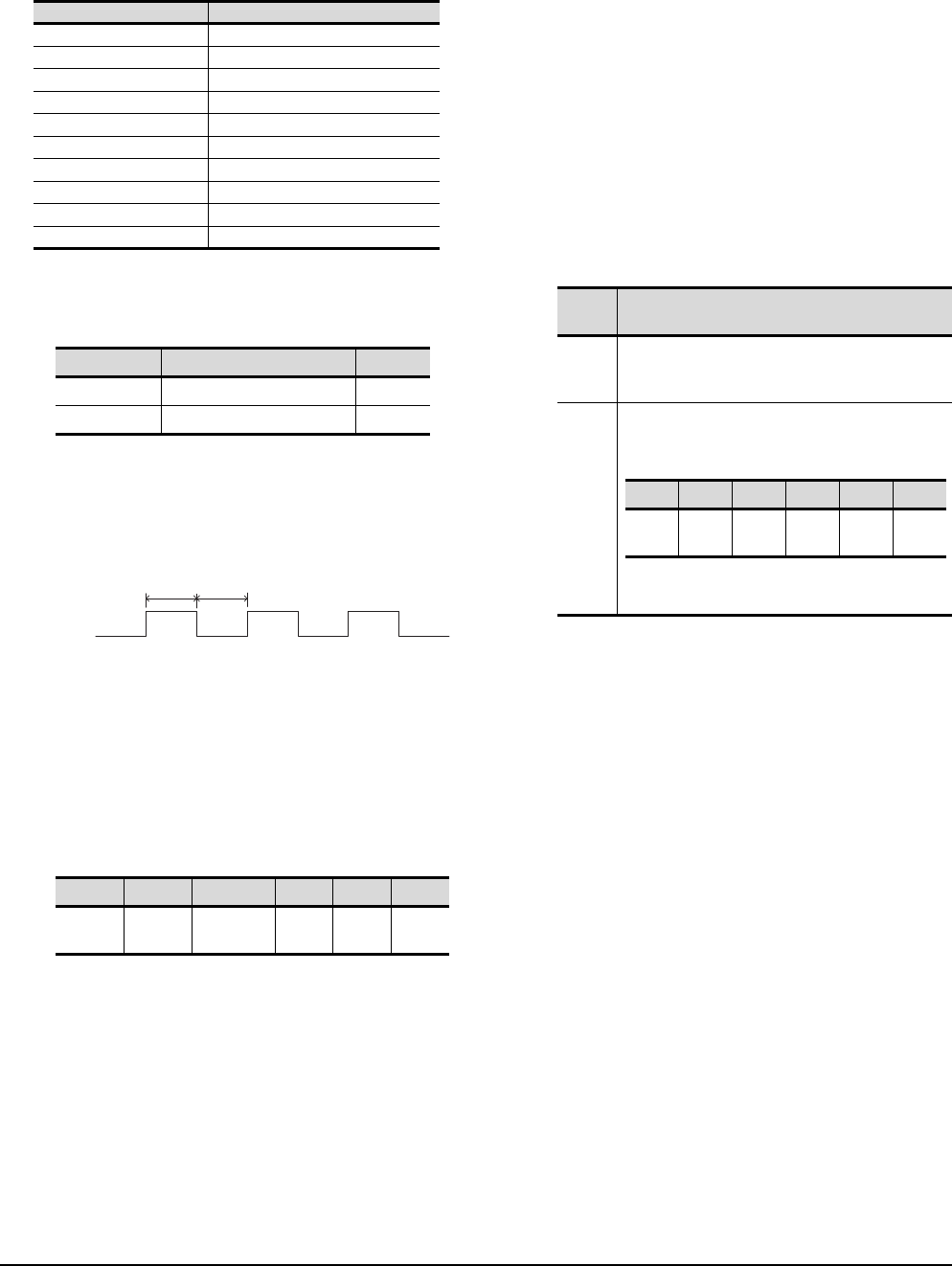
(2) Assignment contents of the PLC side word device
The following table shows the device assignment
contents when setting [Head Device (10 Points)] to
"D0".
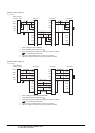
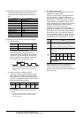
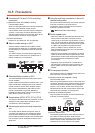
(3) Details on the word device assignment contents
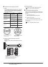
(a) Control signal 1-1
< 10 second cycle flicker signal
*1
>
By the repetition of turning ON/OFF every 5
seconds, the connection between GT01-RS4-M
and the PLC can be confirmed on the PLC side.
When no repetition of this ON/OFF is observed,
GT01-RS4-M is not connected to the PLC.
*1 When writing or clearing data on the program area from the
personal computer to the PLC using FA transparent function,
flicker of the signal as shown above may be temporarily
stopped.
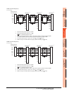
(b) Station information notification signal
*2
This signal notifies the status of the slave station
(GOT) which is connected to the master station
(GT01-RS4-M). Only the bit corresponding to the
number of connected slave station (GOT) is turned
ON and other bits are turned OFF.
• 1: Connected
• 0: Unconnected (Including communication error
status)
*2 When the communication between GT01-RS4-M and the
PLC becomes faulty, the station information notification
signal is not updated.
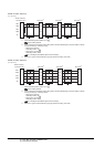
(c) Slave station control signal
This signal controls slave stations which are not
updated by the master station.
Usually, the master station accesses all stations
(up to 16 stations). In addition, if stations are
temporarily in communication error due to a power
disconnection or screen data transfer during the
steady operation, the automatic recovery of the
station is executed for one station per ten seconds.
Therefore, the automatic recovery may take
maximum 2 minutes and 30 seconds.
Using this control signal, the number of slave
stations to be monitored by the master station can
be reduced to the actual number of slave stations
to be used by a user. This makes the automatic
recovery processing smooth. If an error occurs in
only one station, the time for the station to recover
automatically can be reduced within 10 seconds.
When the bits are off and the master station and
the slave stations are in communication, the
communication with the corresponding slave
stations is disconnected if the above corresponding
bits are turned on.
Device Description
D0 (Head device+0) Control signal 1-1
D1(Head device+1) Station information notification signal
D2(Head device+2) (Reserve)
D3(Head device+3) (Reserve)
D4(Head device+4) (Reserve)
D5(Head device+5) Slave station control signal
D6(Head device+6) (Reserve)
D7(Head device+7) (Reserve)
D8(Head device+8) (Reserve)
D9(Head device+9) (Reserve)
Bit position Description
bit0 10 second cycle flicker signal
bit1 to 15 (Reserve)
bit15 bit14 .................. bit2 bit1 bit0
Station
No. 15
Station
No. 14
..................
Station
No. 2
Station
No. 1
Station
No. 0
OFF
ON
5sec
5sec
Device
value
Action
0
The master station accesses all the slave stations
(station 0 to 15). When the multi-drop system
information is not used, the operation is the same.
Other
than 0
Turning on the bit corresponding to a station No.
disconnects the specified slave station from the
master station.
1...Connected
0...Unconnected
bit15 bit14 .......... bit2 bit1 bit0
Station
No. 15
Station
No. 14
..........
Station
No. 2
Station
No. 1
Station
No. 0