


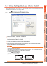
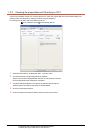
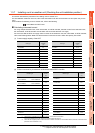
1. PREPARATORY PROCEDURES FOR MONITORING
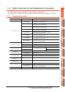
1.3 Option Devices for the Respective Connection
1 - 23
1
PREPARATORY
PROCEDURES FOR
MONITORING
2
DEVICE RANGE
THAT CAN BE SET
3
ACCESS RANGE
FOR MONITORING
4
HOW TO MONITOR
REDUNTANT
SYSTEM
5
BUS CONNECTION
6
DIRECT
CONNECTION TO
CPU
7
COMPUTER LINK
CONNECTION
8
ETHERNET
CONNECTION
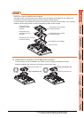
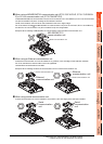
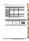
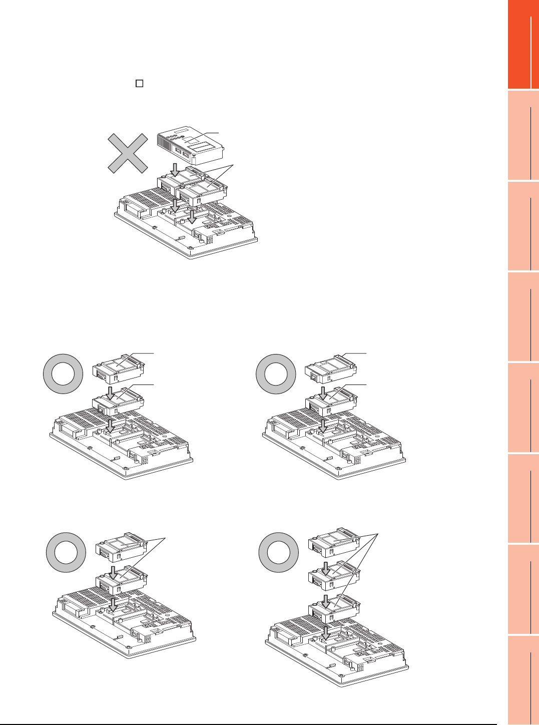
When using a MELSECNET/10 communication unit (GT15-75J71LP23-Z, GT15- 75J71BR13-
Z) or CC-Link communication unit (GT15-75J61BT13-Z)
Install a MELSECNET/10 communication unit (GT15-75J71LP23-Z, GT15-75J71BR13-Z) or CC-Link communication
unit (GT15-75J61BT13-Z) at the 1st stage of the extension interface.
These communication units cannot be used if installed in the 2nd or higher stage.
For GT16 and the GT155 , the MELSECNET/10 communication unit (GT15-75J71LP23-Z, GT15- 75J71BR13-Z)
and the CC-Link communication unit (GT15-75J61BT13-Z) are not applicable.
Example: When installing a MELSECNET/10 communication unit and a serial communication unit
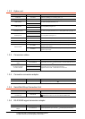
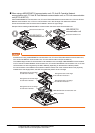
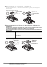
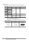
When using an Ethernet communication unit
An Ethernet communication unit can be installed in any position (1st to 3rd stage) of the extension interface.
For GT16, the Ethernet communication unit is not applicable.
Use the Ethernet interface built in the GOT.
Example: When installing an Ethernet communication unit and a serial communication unit
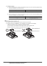
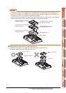
When using a serial communication unit
A serial communication unit can be installed in any position (1st to 3rd stage) of the extension interface.
Serial communication unit
MELSECNET/10
communication unit
Serial communication unit
Ethernet
communication unit
Ethernet
communication unit
Serial communication unit
Serial
communication
unit
Serial
communication
unit