


15 - 44
15. INVERTER CONNECTION
15.6 Device Range that Can Be Set
15.6 Device Range that Can Be Set
The device ranges of controller that can be used for GOT
are as follows.
Note that the device ranges in the following tables are the
maximum values that can be set in GT Designer3.
The device specifications of controllers may differ
depending on the models, even though belonging to the
same series.
Please make the setting according to the specifications of
the controller actually used.
When a non-existent device or a device number outside
the range is set, other objects with correct device settings
may not be monitored.
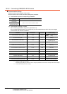
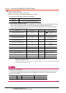
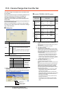
Setting item
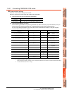
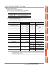
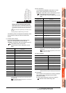
*1 The following shows the relation between the inverter station
numbers and the GOT data register.
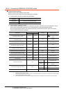
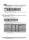
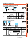
(1) Setting the device by inputting directly from the
keyboard
When setting the device by inputting directly from the
keyboard, set the items as follows.
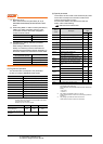
Inverter (FREQROL 500/700 series)
*1 When creating the screen, designate only either of
programmed operation (PG) device or parameter (Pr)
device.
Do no designate both PG (PG0 to PG89) and Pr (Pr900 to
Pr905) devices.
*2 Only 16-bit (1-word) designation is possible.
*3 Only reading is possible.
*4 Precautions for PU operation mode
When the GOT is connected to the PU connector and the
operation mode is set to the PU operation mode, the multi-
speed operation (W3 to W7, SP121, SP122) cannot be used.
For using the multi-speed operation, follow either of the
operations as below.
• Connect the GOT to the RS-485 terminal and set the
operation mode to the NET operation mode (Computer
link operation mode), and then operate the inverter.
• Change the motor speed with the set frequency (SP109,
SP110), and then operate the inverter with the forward or
reverse rotation (WS1, WS2, SP121, SP122).
*5 Precautions for WS devices
Only writing is possible for WS devices.
More than one WS cannot turn on at once.
(Except the turned on WS device, the other WS devices turn
off.)
Bits of SP122 (word device) and SP121 (word device) are
assigned to WS0 to WS7 and WS8 to WS15 respectively.
When more than one WS turns on at once, convert the
values for the bit devices that are assigned to the word
device into values for the word device. Write the converted
values into SP122 or SP121.
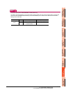
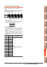
• Setting High speed operation command (WS5), Middle
speed operation command (WS4), and Low speed
operation command (WS3)
When setting High speed operation command (WS5),
Middle speed operation command (WS4), and Low speed
operation command (WS3), write numerical values to
device SP122 as necessary.
As the following figure shows, each operation mode is
assigned to device SP122.
The following shows an example for Forward rotation
command (WS1) and Low speed operation command
(WS3).
Item Description
Device
Set the device name, device number, and bit number.
The bit number can be set only by specifying the bit of word
device.
Station
No.
Monitors the inverter of the specified station No.
0 to 31: To monitor the inverter of the specified
station No.
100 to 115: To specify the station No. of the inverter
to be monitored by the value of GOT data register
(GD).
*1
Information
Displays the device type and setting range which are
selected in [Device].
Station
No.
GOT data register (GD) Setting range
100 GD10 0 to 31
(If setting a value
outside the
range above, a
device range
error occurs)
101 GD11
::
114 GD24
115 GD25
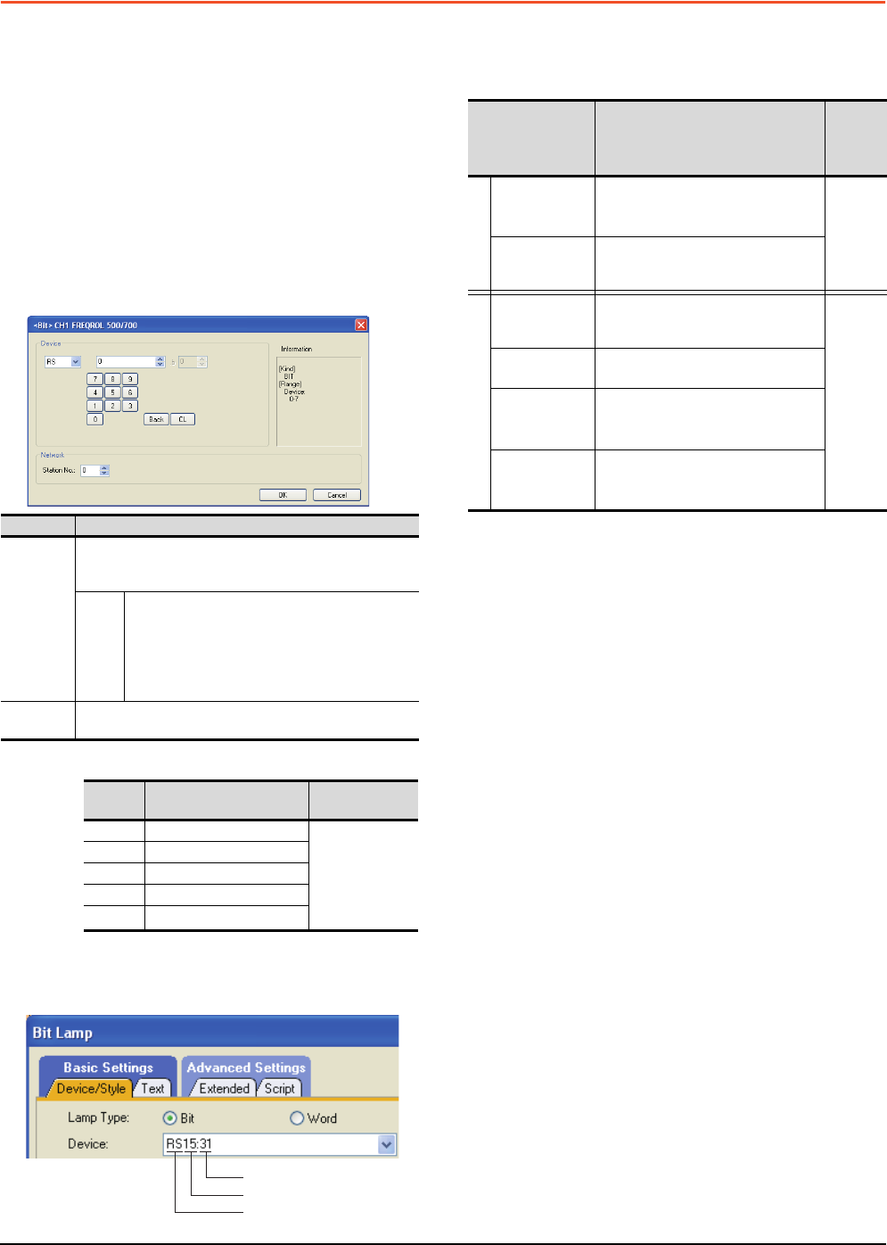
Station No.
Device number
Device name
Device name Setting range
Device
No.
represen
tation
Bit device
Inverter
status monitor
(RS)
*3
RS0: 0 to RS15: 31
RS0: 100 to RS15: 115
Decimal
Run command
(WS)
*4*5
WS0: 0 to RS15: 31
WS0: 100 to RS15: 115
Word device
Alarm definition
(A)
*2*3
A0: 0 to A7: 31
A0: 100 to A7: 115
Decimal
Parameter (Pr)
*1*2
Pr0: 0 to Pr999: 31
Pr0: 100 to Pr999: 115
Programmed
operation
(PG)
*1*2
PG0: 0 to PG89: 31
PG0: 100 to PG89: 115
Special
parameter
(SP)
*2*4
SP108: 0 to SP127: 31
SP108: 100 to SP127: 115