


5. BUS CONNECTION
5.3 GOT Side Settings
5 - 31
1
PREPARATORY
PROCEDURES FOR
MONITORING
2
DEVICE RANGE
THAT CAN BE SET
3
ACCESS RANGE
FOR MONITORING
4
HOW TO MONITOR
REDUNTANT
SYSTEM
5
BUS CONNECTION
6
DIRECT
CONNECTION TO
CPU
7
COMPUTER LINK
CONNECTION
8
ETHERNET
CONNECTION
POINTPOINTPOINT
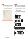
(1) Communication interface setting by Utility
The communication interface setting can be changed
on the Utility's [Communication Settings] after writing
[Communication Settings] of project data.
For details on the Utility, refer to the following manual.
GT User's Manual
(2) Precedence in communication settings
When settings are made by GT Designer3 or the
Utility, the latest setting is effective.
(3) When changing Stage No. and Slot No.
Change these settings with the PLC CPU turned
OFF, and then reapply the power to the PLC CPU
and GOT.
Failure to do so may generate a system alarm
(No.487).
HINTHINTHINT
Cutting the portion of multiple connection of the
controller
By setting GOT internal device, GOT can cut the
portion of multiple connection of the controller. For
example, faulty station that has communication
timeout can be cut from the system.
For details of the setting contents of GOT internal
device, refer to the following manual.
GT Designer3 Version Screen Design Manual
(Fundamentals)
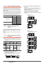
Setting Stage No. and Slot No.
POINTPOINTPOINT
Before setting Stage No. and Slot No.
The PLC CPU recognizes the GOT as follows.
• QCPU (Q mode)
: Intelligent function module of 16 I/O points
• Other than QCPU (Q mode)
: Intelligent function module of 32 I/O points
At the [Detail setting], assign the GOT to an empty I/O
slot on the PLC CPU.
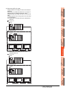
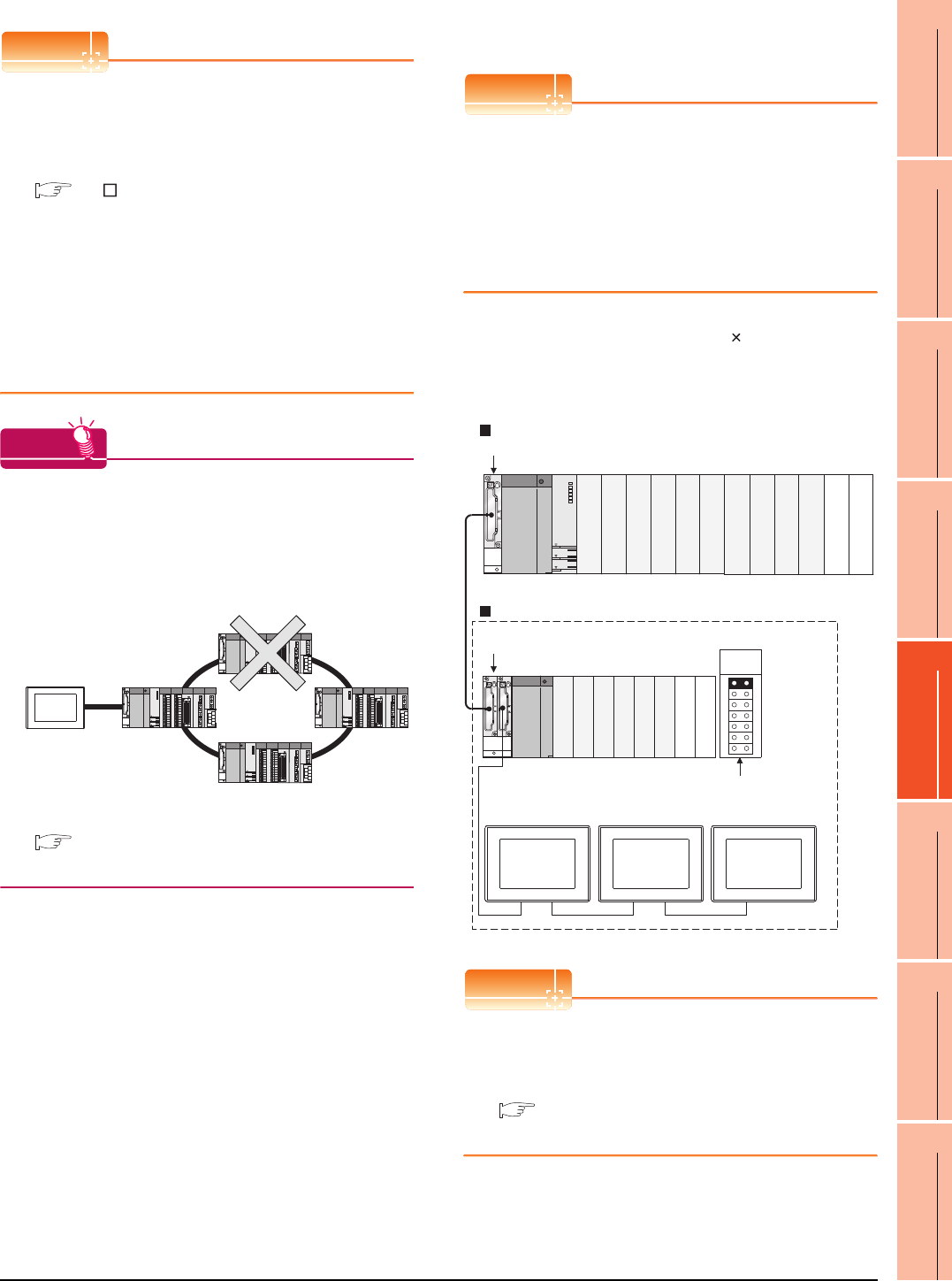
(1) When connecting to QCPU (Q mode)
Set an additional stage (16 points 10 slots) for GOT
connection, and assign a GOT to one of the I/O slots.
(The GOT cannot be assigned to empty slots of the
main base unit or extension base unit.)
POINTPOINTPOINT
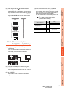
When using the bus extension connector box
Set the Stage No. switch on the bus extension
connector box to the same Stage No. as the GOT.
For setting details, refer to the following manual:
A9GT-QCNB Bus Extension Connector Box
User's Manual
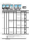
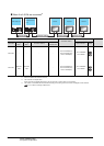
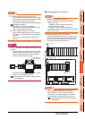
Disconnect the
faulty station
Q312B
Q68B
Main base unit
Stage No. :2
Slot No. :0
Stage No. :2
Slot No. :1
Stage No. :2
Slot No. :2
Extension base unit
Stage No. setting
connector
Extension
stage 1
Empty
Empty
Empty
Empty