


5. BUS CONNECTION
5.4 Precautions
5 - 37
1
PREPARATORY
PROCEDURES FOR
MONITORING
2
DEVICE RANGE
THAT CAN BE SET
3
ACCESS RANGE
FOR MONITORING
4
HOW TO MONITOR
REDUNTANT
SYSTEM
5
BUS CONNECTION
6
DIRECT
CONNECTION TO
CPU
7
COMPUTER LINK
CONNECTION
8
ETHERNET
CONNECTION
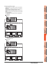
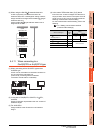
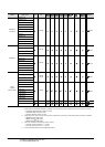
(4) When using the QA1S6 B extension base unit
A GOT is physically connected to the last of all
extension base units. In the Stage No. setting, however,
assign the GOT as a stage next to the last Q B type
extension base unit.
Assign the QA1S6 B type extension base unit as a
stage next to the GOT.
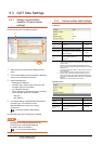
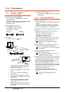
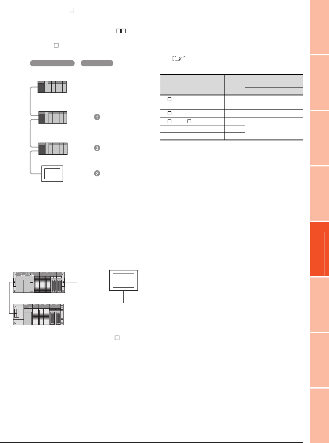
5.4.11 When connecting to a
QnA(S)CPU or An(S)CPU type
(1) When connecting with a QnASCPU type and an
AnSCPU type
A GOT can be connected to an extension connector on
only one side of the main base unit.
(Concurrently connecting GOTs to extension
connectors on both sides is not allowed)
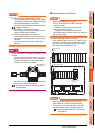
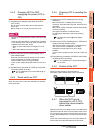
(2) In the case of Q4A(R)CPU, Q3ACPU, A3 CPU,
A4UCPU
Empty I/O slots are required within the max. number of
extension stages.
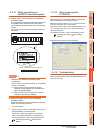
(3) For A0J2HCPU
Assign the GOT to the I/O slots 0 to 3 of extension
stage 1.
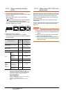
(4) In the case of CPUs other than (2) (3) above
Even if the max. number of stages are used with no
empty I/O slots, when there is a free space of 32 I/O
points or more, a GOT can be connected under the
following communication interface setting.
For the communication interface setting, refer to the
following.
5.3.1 Setting communication interface
(Communication settings)
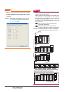
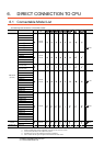
Q38B
Main base unit
Q68B
Extension base unit
QA1S68B
Extension base unit
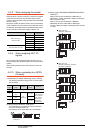
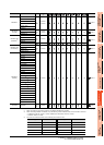
Stage No.
Connection method
When connecting to
Max.
stage
No.
Communication interface
setting
Stage No. Slot No.
A1 CPU/A2USCPU(-S1)
/QnAS(H)CPU(-S1)
12 0
A2 CPU/Q2ACPU
34 0
A3 CPU/A4 CPU
7
Cannot be used
Q3ACPU/Q4ACPU 7
A0J2HCPU 1