


4 - 8
4. HOW TO MONITOR REDUNTANT SYSTEM
4.1 Connection to Remote I/O Station in MELSECNET/H Network System
4.1 Connection to Remote I/O Station in MELSECNET/
H Network System
4.1.1 Direct CPU connection (Direct CPU connection to the remote I/O station)
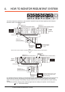
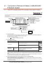
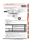
This section explains the direct CPU connection that connects the GOT to the remote I/O station of the MELSECNET/H
network system.
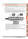
The following shows an example of connecting the GOT to the remote I/O station of the MELSECNET/H network system.
(1) Connection method
Connect the GOT to the RS-232 interface of the network module (QJ72LP25-25, QJ72LP25G, QJ72BR15) on
the remote I/O station of the MELSECNET/H network system.
For details, refer to the following.
6. DIRECT CONNECTION TO CPU
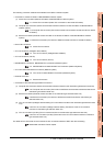
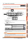
(2) GT Designer3 setting
Set GT Designer3 as follows.
In this case, the GOT monitoring is performed by transient transmission of the MELSECNET/H network
system.Therefore, a longer time-lag occurs for displaying objects compared with directly monitoring the PLC
CPU.
For displaying objects with a shorter time-lag, execute the cyclic transmission so that the GOT can monitor link
devices B and W of the host station set in the MELSECNET/H network.
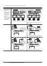
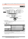
(3) Monitoring target change when system switching occurs in a redundant system
When the system switching occurs, the multiplexed remote sub master station switched to the control system
takes over the master operation of MELSECNET/H.
Since the GOT monitors the master station, the monitoring target is automatically changed to the PLC CPU that
is operating as the master.
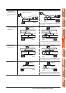
Setting item Settings Model
Controller Type
MELSEC-QnA/Q/QS, MELDAS C6*
MELSEC-QnA/Q, MELDAS C6*
Device setting
(Network setting)
Host Host
Remote master
station
Other (NW No. 1 (network No. of remote I/O network),
Station No. 0 (master station))
Q Redundant Setting Do not set the item.
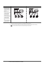
Monitor target
MELSECNET/H remote I/O network
CPU direct connection
GOT
Network No. 1, Station No. 0
(Multiplexed remote master station)
Control system
(System A)
Q25PRHCPU
QJ71LP21-25
QJ71BR11
QJ71E71-100
QJ61BT11N
Network No. 1, Station No. 1
(Multiplexed remote sub master station)
Standby system
(System B)
Q25PRHCPU
QJ71LP21-25
QJ71BR11
QJ71E71-100
QJ61BT11N
QJ72LP25-25
QJ71C24N
Network No. 1, Station No. 2
(Remote I/O station)
Empty
Empty
Power supply
module
Empty
Power supply
module
Empty
Power supply
module