


16 - 24
16. SERVO AMPLIFIER CONNECTION
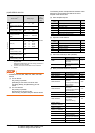
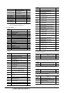
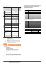
16.6 Device Range that Can Be Set
*1 For the parameters prefixed by an asterisk (*), setting
becomes effective when the power is turned off once and
back on after setting the parameter data.
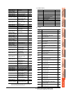
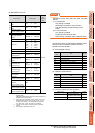
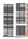
(e) Status display
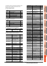
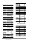
(f) Alarm
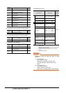
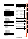
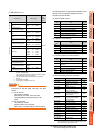
(g) External I/O signal
(h) Input signal for test operation (for test operation)
(i) Forced output of signal pin (for test operation)
(j) Set data (for test operation)
Device name Item
Symbol
*1
PRM70, PRM1070
Command pulse multiplying
factor numerator 3
CMX3
PRM71, PRM1071
Command pulse multiplying
factor numerator 4
CMX4
PRM72, PRM1072
Internal speed command4/limit4
SC4
PRM73, PRM1073
Internal speed command5/limit5
SC5
PRM74, PRM1074
Internal speed command6/limit6
SC6
PRM75, PRM1075
Internal speed command7/limit7
SC7
PRM76, PRM1076 Internal torque limit 2 TL2
PRM77 to PRM84,
PRM1077 to PRM1084
For manufacturer setting ―
Device
name
Item Symbol
ST0 Cumulative feedback pulses ―
ST1 servo motor speed ―
ST2 Droop pulses ―
ST3 Cumulative command pulses ―
ST4 Command pulse frequency ―
ST5 Analog speed command voltage/limit voltage ―
ST6 Analog torque command voltage/limit voltage ―
ST7 Regenerative load ratio ―
ST8 Effective load ratio ―
ST9 Peak load ratio ―
ST10 Instantaneous torque ―
ST11 Within one-revolution position ―
ST12 ABS counter ―
ST13 load inertia moment ratio ―
ST14 Bus voltage ―
Device
name
Item Symbol
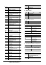
AL0 Current alarm number ―
AL1 Detailed data of current alarms ―
AL11
Servo status when alarm occurs cumulative
feedback pulses
―
AL12
Servo status when alarm occurs
servo motor speed
―
AL13 Servo status when alarm occurs droop pulses ―
AL14
Servo status when alarm occurs cumulative
command pulses
―
AL15
Servo status when alarm occurs command
pulse frequency
―
AL16
Servo status when alarm occurs analog
speed command voltage/limit voltage
―
AL17
Servo status when alarm occurs analog
torque command voltage/limit voltage
―
AL18
Servo status when alarm occurs regenerative
load ratio
―
AL19
Servo status when alarm occurs effective load
ratio
―
AL20
Servo status when alarm occurs peak load ratio
―
AL21
Servo status when alarm occurs
instantaneous torque
―
AL22
Servo status when alarm occurs within one-
revolution position
―
AL23 Servo status when alarm occurs ABS counter ―
AL24
Servo status when alarm occurs
load inertia moment ratio
―
AL25 Servo status when alarm occurs bus voltage ―
AL200
Alarm number from alarm history
most recent alarm
―
AL201
Alarm number from alarm history
first alarm in past
―
AL202
Alarm number from alarm history
second alarm in past
―
AL203
Alarm number from alarm history
third alarm in past
―
AL204
Alarm number from alarm history
fourth alarm in past
―
AL205
Alarm number from alarm history
fifth alarm in past
―
AL210
Alarm occurrence time in alarm history
most recent alarm
―
AL211
Alarm occurrence time in alarm history
first alarm in past
―
AL212
Alarm occurrence time in alarm history
second alarm in past
―
AL213
Alarm occurrence time in alarm history
third alarm in past
―
AL214
Alarm occurrence time in alarm history
fourth alarm in past
―
AL215
Alarm occurrence time in alarm history
fifth alarm in past
―
AL230
Detailed alarm from alarm history
most recent alarm
―
AL231
Detailed alarm from alarm history
first alarm in past
―
AL232
Detailed alarm from alarm history
second alarm in past
―
AL233
Detailed alarm from alarm history
third alarm in past
―
AL234
Detailed alarm from alarm history
fourth alarm in past
―
AL235
Detailed alarm from alarm history
fifth alarm in past
―
Device
name
Item Symbol
DI0 External input pin statuses ―
DO0 External output pin statuses ―
Device
name
Item Symbol
TMI0 Input signal status for test operation ―
Device
name
Item Symbol
TMO0 Forced output status of signal pin ―
Device
name
Item Symbol
TMD0 Writes the speed (test mode) ―
TMD1
Writes the acceleration/deceleration time
constant (test mode)
―
TMD2
Writes the moving distance in pulses (test
mode)
―
Device
name
Item Symbol