6. DIRECT CONNECTION TO CPU
6.2 System Configuration
6 - 15
1
PREPARATORY
PROCEDURES FOR
MONITORING
2
DEVICE RANGE
THAT CAN BE SET
3
ACCESS RANGE
FOR MONITORING
4
HOW TO MONITOR
REDUNTANT
SYSTEM
5
BUS CONNECTION
6
DIRECT
CONNECTION TO
CPU
7
COMPUTER LINK
CONNECTION
8
ETHERNET
CONNECTION
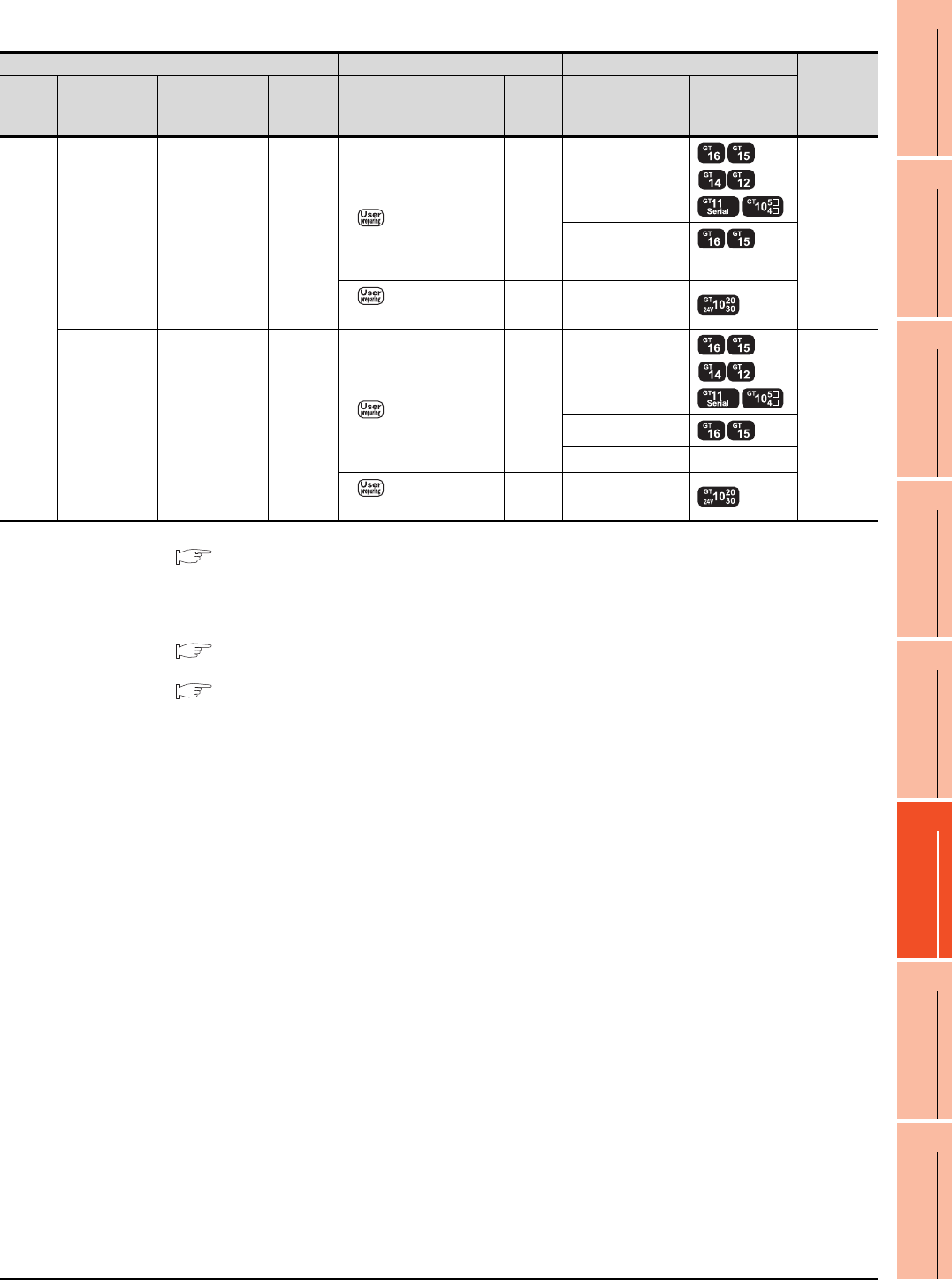
When connecting to FX3G (RS-232 connection)
*1 For details of the GOT multi-drop connection, refer to the following.
19. GOT MULTI-DROP CONNECTION
*2 When the function expansion board (communication board) and the function adapter are connected, a GOT and a peripheral
such as a PC with GX Developer installed can be connected to them individually.
GT14, GT12, GT11 and GT10 are available for the multiple-GT14, GT12, GT11, GT10 connection function to connect up to two
GOTs.
20. MULTIPLE-GT14, GT12, GT11, GT10 CONNECTION FUNCTION
*3 When using function expansion boards or function adapters, confirm the communication settings.
6.5 Precautions Connection to FXCPU (2)When connecting with function extension board or communication special
adapter
*4 Use the RS-232 connection model.
PLC Connection cable GOT
Number of
connectable
equipment
*2
Model
name
Function
expansion
board
*3
Function
adapter
*3
Communi
cation
type
Cable model
Connection diagram
number
Max.
distance
Option device Model
FX
3G
FX3G-232-BD - RS-232
GT01-C30R2-9S(3m)
or
RS232 connection
diagram 1)
15m
- (Built into GOT)
1 GOT for 1
function
expansion
board
GT15-RS2-9P
GT01-RS4-M
*1
-
RS232 connection
diagram 4)
15m - (Built into GOT)
*4
-
FX
3G-CNV-ADP
+
FX
3U-232ADP
RS-232
GT01-C30R2-9S(3m)
or
RS232 connection
diagram 1)
15m
- (Built into GOT)
1 GOT for 1
function
adapter
GT15-RS2-9P
GT01-RS4-M
*1
-
RS232 connection
diagram 4)
15m - (Built into GOT)
*4


