


4. HOW TO MONITOR REDUNTANT SYSTEM
4.10 Switch the Monitor Target to the Control System Using the Script Function
4 - 31
1
PREPARATORY
PROCEDURES FOR
MONITORING
2
DEVICE RANGE
THAT CAN BE SET
3
ACCESS RANGE
FOR MONITORING
4
HOW TO MONITOR
REDUNTANT
SYSTEM
5
BUS CONNECTION
6
DIRECT
CONNECTION TO
CPU
7
COMPUTER LINK
CONNECTION
8
ETHERNET
CONNECTION
4.10 Switch the Monitor Target to the Control System
Using the Script Function
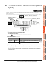
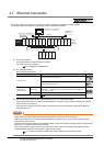
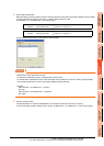
The following explains how to create a script screen, to be used for the MELSECNET/H or MELSECNET/10
connection (network system), or Ethernet connection, that automatically changes the monitoring target (Station No.)
at the occurrence of system switching even if the Q redundant setting is not made.
The script executes the station number switching function or screen switching function.
The following shows the advantages and disadvantages of the station number switching function and screen
switching function.
The following explains how to use each function.
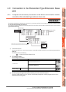
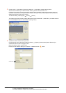
4.10.1 Method for using the station number switching function
• As a feature of this function, monitor screens for Station No. 1 (control system) and Station No. 2 (standby system)
can be created on one screen.
• If the system switching occurs, the GOT can change the monitoring target to the control system PLC CPU on the
same monitor screen.
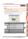
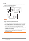
• To achieve this, the script of the GOT monitors the special relay SM1515 (Control system identification flag) of the
PLC CPU and stores the station number of the latest control system into the station number switching device.
• Restrictions: Some objects do not allow the station number to be switched.
GT Designer3 Version Screen Design Manual
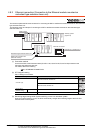
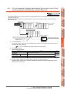
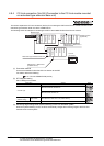
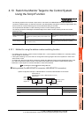
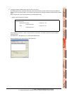
Setting method (For MELSECNET/H connection, MELSECNET/10 connection)
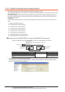
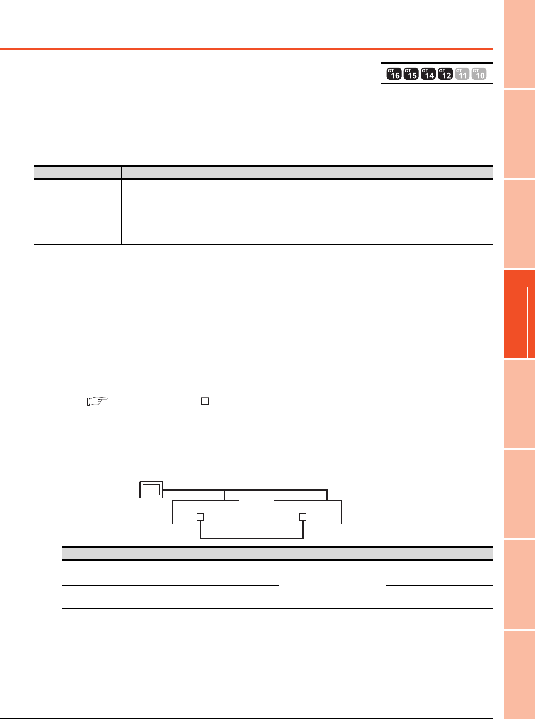
System configuration example 1: MELSECNET/H connection, MELSECNET/10 connection
Function Advantage Disadvantage
Station number switching
function
The monitor screens for Station No. 1 (control system)
and Station No. 2 (standby system) can be created on one
screen.
Some objects do not allow the station number to be
switched.
Screen switching function
All objects can be used since monitor screens are created
for each station number.
Monitor screens must be created separately for Station
No. 1 (control system) and Station No. 2 (standby
system).
Connected module Network No. Station No.
MELSECNET/H network module of control system
1
1
MELSECNET/H network module of standby system 2
GOT connected to MELSECNET/H network or MELSECNET/10
network
3
MELSECNET/H
(MELSECNET/H mode or MELSECNET/10 mode)
Network No. 1
GOT
Station
No. 3
Control system
(System A)
Q25PRH
CPU
QJ71
BR11
Standby system
(System B)
Station No. 1
Q25PRH
CPU
QJ71
BR11
Station No. 2