18. CNC CONNECTION
18.5 CNC Side Settings
18 - 19
17
ROBOT
CONTROLLER
CONNECTION
18
CNC CONNECTION
19
GOT MULTI-DROP
CONNECTION
20
MULTIPLE-GT14, GT12,
GT11, GT10
CONNECTION FUNCTION
21
MULTI-CHANNEL
FUNCTION
22
FA TRANSPARENT
FUNCTION
18.5.2 CC-Link (ID) connection
Parameter setting
Set parameters related to CC-Link connection with GX
Developer and write them to CNC by PLC. However, in
the case of using the local stations, it is not necessary
to set the network parameters.
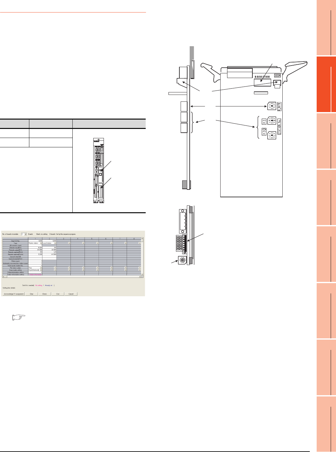
(1) Master station parameter
It is necessary to set and write the network parameters
to CNC with GX Developer. The following shows an
example of parameter settings.Set the first I/O No. as
follows according to the expansion slot to which the unit
is inserted.
(a) Start I/O No.
(b) Example of GX Developer setting
For details of the parameter setting, refer to the
following.
C6/C64/C64T NETWORK INSTRUCTION
MANUAL BNP-B2373
Expansion unit settings
Make the communication settings by the setting switch
in the expansion unit (FCU6-HR865).
(1) Expansion unit
Slot Start I/O No.
EXT1 0200
EXT2 0280
EXT1
EXT2
4)
3)
2)
1)
1)
2)


