


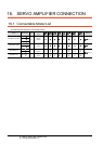
15. INVERTER CONNECTION
15.6 Device Range that Can Be Set
15 - 45
9
MELSECNET/H
CONNECTION (PLC
TO PLC NETWORK)
10
MELSECNET/10
CONNECTION (PLC
TO PLC NETWORK)
11
CC-Link IE CONTROLLER
NETWORK
CONNECTION
12
CC-Link IE FIELD
NETWORK
CONNECTION
13
CC-Link CONNECTION
(INTELLIGENT DEVICE
STATION)
14
CC-Link
CONNECTION
(Via G4)
15
INVERTER
CONNECTION
16
SERVO AMPLIFIER
CONNECTION
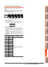
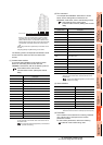
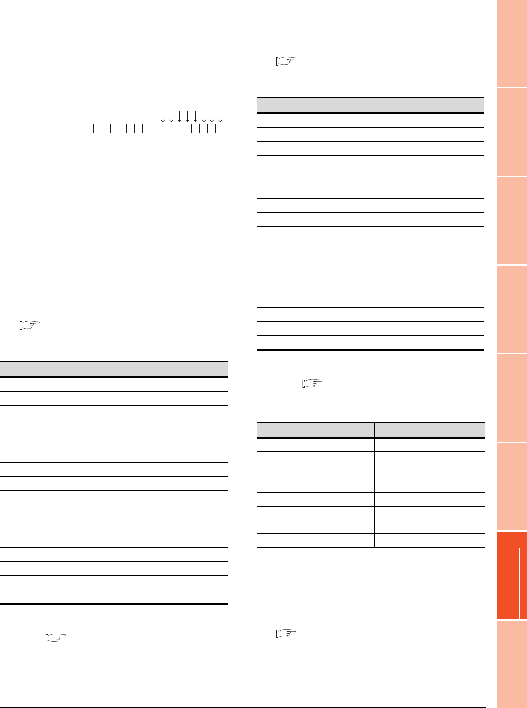
Write [1] to each bit corresponding to Forward rotation
command (WS1) and Low speed operation command
(WS3) of device SP122. The value will be 000AH in this
example. When writing the value to device SP122 actually,
convert 000AH to decimal number and write the value
[10].
When using a WS device, [Alternate] of a bit switch cannot
be used.
Use [Set], [Reset], and [Momentary] of a bit switch.
The following shows correspondences between virtual
inverter devices used in the GOT and data of the
inverter.
(1) Inverter status monitor
An example with FREQROL-A700 series is shown
below. For the setting items of other than the
FREQROL-A700 series, refer to the following manual.
User's Manual of the used inverter
(communication function (setting item and set
data))
*1 The description (function of input terminal) may be changed
by the parameter of the inverter side. Check the function of
the inverter used.
Inverter User's Manual (Application) Communication
operation and setting
(2) Run command
An example with FREQROL-A700 series is shown
below. For the setting items of other than the
FREQROL-A700 series, refer to the following manual.
User's Manual of the used inverter
(Communication function (Setting item and set
data))
*1 The data (function of input terminal) may be changed by the
parameter of the inverter side. Check the function of the
inverter used.
Inverter User's Manual (Application) Communication
operation and setting
(3) Alarm definition
*1 Only reading is possible for A0 to A7.
These devices cannot be used for a write object (numerical input etc.).
(4) Parameter
The numbers of virtual devices for inverter (parameter
(Pr)), used by GOT, correspond to the inverter
parameter numbers.
For the inverter parameters, refer to the following.
Manual of the inverter being used
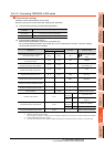
Device name
Description
*1
RS0 Inverter running (RUN)
RS1 Forward rotation (STF)
RS2 Reverse rotation (STR)
RS3 Up to frequency (SU)
RS4 Overload (OL)
RS5 Instantaneous power failure (IPF)
RS6 Frequency detection (FU)
RS7 Fault (ABC1)
RS8 ABC2
RS9 -
RS10 -
RS11 -
RS12 -
RS13 -
RS14 -
RS15 Fault occurrence
Device SP122
b15 b7 b0
0000000000001010
WS7: Output stop(MRS)
WS6: Second function selection(RT)
WS5: High speed operation command(RH)
WS4: Middle speed operation command(RM)
WS3: Low speed operation command(RL)
WS2: Reverse rotation command(STR)
WS1: Forward rotation command(STF)
WS0: Current input selection(AU)
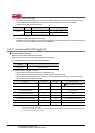
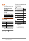
Device name
Description
*1
WS0 Current input selection (AU)
WS1 Forward rotation command (STF)
WS2 Reverse rotation command (STR)
WS3 Low speed operation command (RL)
WS4 Middle speed operation command (RM)
WS5 High speed operation command (RH)
WS6 Second function selection (RT)
WS7 Output stop (MRS)
WS8 Jog operation (JOG)
WS9
Selection of automatic restart after instantaneous
power failure (CS)
WS10 Start self-holding (STOP)
WS11 Reset (RES)
WS12 -
WS13 -
WS14 -
WS15 -
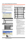
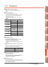
Device name
*1
Description
A0 Second alarm in past
A1 Latest alarm
A2 Fourth alarm in past
A3 Third alarm in past
A4 Sixth alarm in past
A5 Fifth alarm in past
A6 Eighth alarm in past
A7 Seventh alarm in past