


8. ETHERNET CONNECTION
8.2 System Configuration
8 - 13
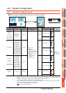
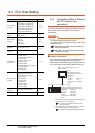
1
PREPARATORY
PROCEDURES FOR
MONITORING
2
DEVICE RANGE
THAT CAN BE SET
3
ACCESS RANGE
FOR MONITORING
4
HOW TO MONITOR
REDUNTANT
SYSTEM
5
BUS CONNECTION
6
DIRECT
CONNECTION TO
CPU
7
COMPUTER LINK
CONNECTION
8
ETHERNET
CONNECTION
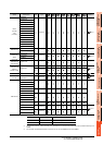
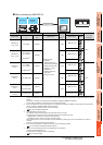
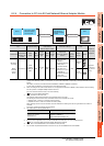
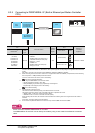
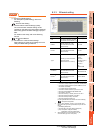
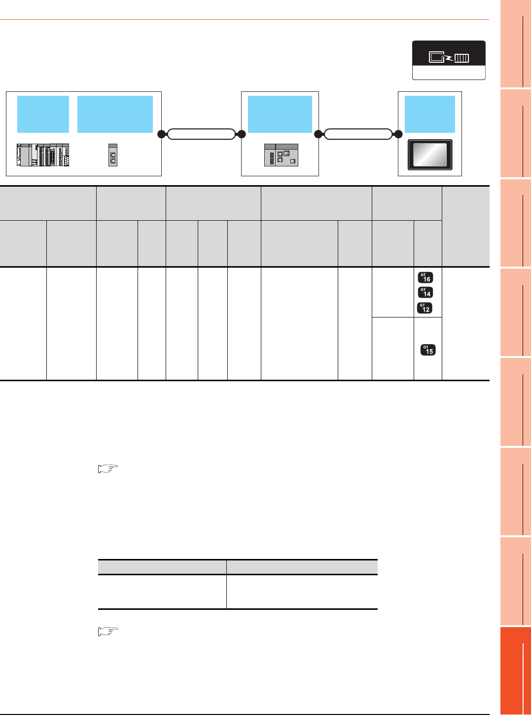
8.2.4 Connection to CC-Link IE Field Network Ethernet Adapter Module
*1 The destination connected with the twisted pair cable varies with the configuration of the applicable Ethernet network system.
Connect to the Ethernet module, hub, transceiver, or other system equipment corresponding to the applicable Ethernet network
system.
Use cables, connectors, and hubs that meet the IEEE802.3 10BASE-T/100BASE-TX standard.
A cross cable is available for connecting the GOT to the Ethernet module.
*2 When connecting GT16 of the function version A to an equipment that meets the 10BASE (-T/2/5) standard, use the switching
hub and operate in a 10Mbps/100Mbps mixed environment.
For how to check the function version, refer to the following.
GT16 User's Manual (Hardware)
*3 A length between a hub and a node.
The maximum distance differs depending on the Ethernet device to be used.
The following shows the number of the connectable nodes when a repeater hub is used.
• 10BASE-T: Max. 4 nodes for a cascade connection (500m)
• 100BASE-TX: Max. 2 nodes for a cascade connection (205m)
When switching hubs are used, the cascade connection between the switching hubs has no logical limit for the number of
cascades.
For the limit, contact the switching hub manufacturer.
*4 Use cables with the following specifications.
*5 For the system configuration on the CC-Link IE Field Network module side, refer to the following manual.
CC-Link IE Field Network Ethernet Adapter Module User's Manual
*6 The number of connectable GOTs for one network is 63 units (at most).
*7 GT14 models compatible with Ethernet connection are only GT1455-QTBDE and GT1450-QLBDE.
CC-Link IE Field
Network Master/
Local module
CC-Link IE
Field Network
Ethernet adapter
module
GOT
QCPU
Connection cable 1) Connection cable 2)
Ethernet(MELSEC),
Q17nNC, CRnD-700
Communication driver
PLC
Connection cable 1)
*4
CC-Link IE
Field Network
Ethernet adapter module
Connection cable 2)
*1
GOT
Number of
connectable
equipment
Model name
CC-Link IE
Field Network
Master/Local
module
Cable
model
Max.
distance
Commu
nication
type
Model
name
Commu
nication
type
Cable model
Connection diagram
number
Maximu
m
segment
length
*3
Option
device
Model
MELSEC-Q
(Q mode)
Motion
Controller
CPU (Q
Series)
QJ71GF11-T2
Double-
shielded
twisted pair
cable
*4
100m
CC-Link
IE
NZ2GF
-ETB
Ethernet
Twisted pair cable
• 10BASE-T
Shielded twisted pair
cable (STP) or
unshielded twisted
pair cable (UTP):
Category 3, 4, and 5
• 100BASE-TX
Shielded twisted pair
cable (STP):
Category 5 and 5e
100m
- (Built into
GOT)
*2
*7
128 GOTs
*6
(recommend
ed to 16 units
or less)
GT15-
J71E71-100
Connector Range
Category 5e or higher
Shielded RJ-45
Cable that satisfies the following specifications:
IEEE802.3 1000BASE-T
ANSI/TIA/EIA-568-B(Category 5e)