


16. SERVO AMPLIFIER CONNECTION
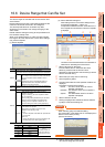
16.6 Device Range that Can Be Set
16 - 25
9
MELSECNET/H
CONNECTION (PLC
TO PLC NETWORK)
10
MELSECNET/10
CONNECTION (PLC
TO PLC NETWORK)
11
CC-Link IE CONTROLLER
NETWORK
CONNECTION
12
CC-Link IE FIELD
NETWORK
CONNECTION
13
CC-Link CONNECTION
(INTELLIGENT DEVICE
STATION)
14
CC-Link
CONNECTION
(Via G4)
15
INVERTER
CONNECTION
16
SERVO AMPLIFIER
CONNECTION
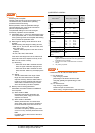
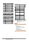
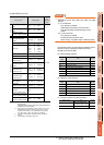
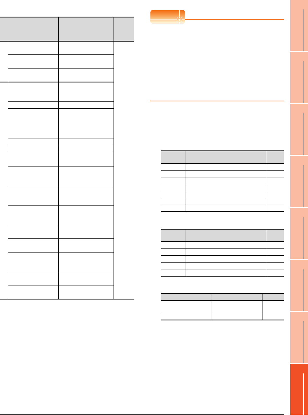
(5) MELSERVO-J2S-*CP
*1 Use PRM0 to PRM90 when writing parameters to the servo
amplifier RAM.
PRM1000 to PRM1090 are used when writing parameters to
E
2
PROM of the servo amplifier.
*2 When writing to a point table, use the area of 1001 to 1031
(E
2
PROM area) of POS, SPD, ACT, DCT, DWL, or AUX.
If writing to the area of 1 to 31 (RAM area) of POS, SPD,
ACT, DCT, DWL, or AUX, the value is not reflected.
*3 The GOT cannot read or write data from/to consecutive
devices.
*4 Only reading is possible for DI0 to DI1.
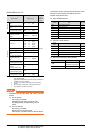
POINTPOINTPOINT
Precautions for SP, OM, TMB, TMI, TMO, and TMD
devices
(1) For bit devices
Only writing is possible.
[Alternate] of a bit switch cannot be used.
Use [Set], [Reset], and [Momentary] of a bit
switch.
(2) For word devices
Only writing is possible.
Numerical input cannot be used.
When writing, use [Word Set] of a data set switch.
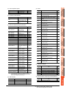
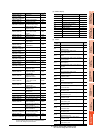
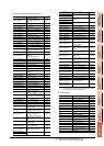
The following shows correspondences between virtual
devices for servo amplifier and data of the servo
amplifier used with the GOT.
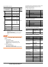
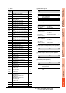
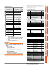
(a) Servo amplifier request
(b) Operation mode selection
(c) Instruction demand (for test operation)
Device name
*3
Setting range
Device
No.
represent
ation
Bit device
Servo amplifier request
(SP)
SP0 to SP6
Decimal
Operation mode selection
(OM)
OM0 to OM4
Instruction demand
(for test operation) (TMB)
TMB0 to TMB1
Word device
Basic parameter
/expansion parameter
(PRM)
*1
PRM0 to PRM90
PRM1000 to PRM1090
Status display (ST) ST0 to ST16
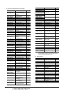
Alarm (AL)
AL0 to AL1
AL11 to AL27
AL200 to AL205
AL210 to AL215
AL230 to AL235
External input (DI)
*4
DI0 to DI2
External output (DO) DO0 to DO1
Point table
(position) (POS)
*2
POS1 to POS31
POS1001 to POS1031
Point table
Point table (speed)
(SPD)
*2
SPD1 to SPD31
SPD1001 to SPD1031
Point table
(acceleration time
constant) (ACT)
*2
ACT1 to ACT31
ACT1001 to ACT1031
Point table
(deceleration time
constant) (DCT)
*2
DCT1 to DCT31
DCT1001 to DCT1031
Point table
(dwell) (DWL)
*2
DWL1 to DWL31
DWL1001 to DWL1031
Point table
(auxiliary function) (AUX)
*2
AUX1 to AUX31
AUX1001 to AUX1031
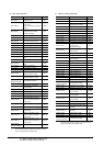
Input signal for test
operation
(for test operation) (TMI)
TMI0
Forced output of signal pin
(for test operation) (TMO)
TMO0
Set data
(for test operation) (TMD)
TMD0 to TMD2
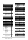
Device
name
Item Symbol
SP0 Status display data clear ―
SP1 Current alarm clear ―
SP2 Alarm history clear ―
SP3 External input signal prohibited ―
SP4 External output signal prohibited ―
SP5 External input signal resumed ―
SP6 External output signal resumed ―
Device
name
Item Symbol
OM0 Normal mode (not test operation mode) ―
OM1 JOG operation ―
OM2 Positioning operation ―
OM3 Motorless operation ―
OM4 Output signal (DO) forced output ―
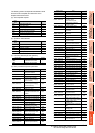
Device name Item Symbol
TMB0
Clears the acceleration/
deceleration time constant
―
TMB1 Temporary stop command ―