1 - 20
1. PREPARATORY PROCEDURES FOR MONITORING
1.3 Option Devices for the Respective Connection
(3) Calculation example
(a) When connecting the GT15-J71BR13, GT15-RS4-9S (3 units), GT15-J71E71-100 (For the gateway function)
and a bar code reader (0.12 A) to the GT1575-V
Since the calculated value is within the capacity of the GOT, they can be connected to the GOT.
(b) When connecting the GT15-J71BR13, GT15-RS4-9S (2 units), GT15-J71E71-100 (For the gateway function)
and a bar code reader (0.12 A) to the GT1585-S
Since the calculated value exceeds the capacity of the GOT, such configuration is not allowed.
When using a bus connection unit
The installation position varies depending on the bus connection unit to be used.
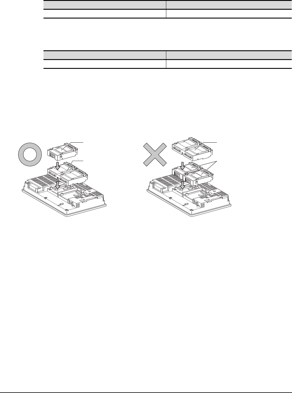
(1) Wide bus units (GT15-75QBUS(2)L, GT15-75ABUS(2)L, GT15-QBUS2, GT15-ABUS2)
Install a bus connection unit in the 1st stage of the extension interface.
If a bus connection unit is installed in the 2nd stage or above, the unit cannot be used.
Example: Installing a bus connection unit and serial communication units
Current supply capacity of GOT (A) Total consumed current (A)
2.2 0.77+0.33+0.33+0.33+0.224+0.12=2.104
Current supply capacity of GOT (A) Total consumed current (A)
1.74 0.77+0.33+0.33+0.224+0.12=1.774
Serial communication unit
Bus connection unit
Bus connection unit
Serial communication unit


