


3 - 14
3. ACCESS RANGE FOR MONITORING
3.3 CC-Link System Access Range for Monitoring
3.3 CC-Link System Access Range for Monitoring
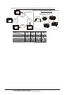
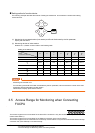
When using Bus connection/CPU direct connection/computer link connection
Only connected stations can be monitored.
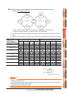
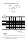
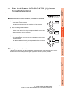
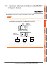
When using CC-Link connection (intelligent device station)
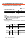
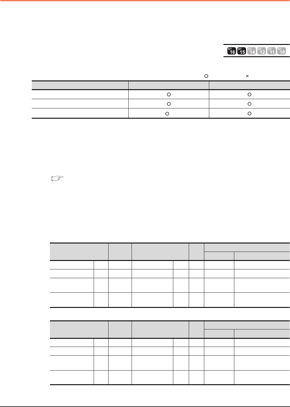
(1) Access range
The master station and local station can be monitored.
: Can be monitored, : Cannot be monitored
*1 Monitoring is available only when the CC-Link communication module is the GT15-J61BT13.
All devices RX, RY, RWw and RWr that are allocated to the master station by the CC-Link parameter setting can
be monitored.
When the monitor target is the multi-PLC system, CPU No. 1 to No. 4 can be monitored.
The device range of RX, RY, RWw, RWr to be allocated to the GOT differs according to the setting of the number
of CC-Link communication units (one station/four station) occupied.
For details on the number of CC-Link stations occupied, refer to the following manual .
User's manual of the CC-Link master unit to be connected
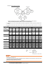
(2) Setting device name and device number
(a) Monitoring devices RX, RY, RWw and RWr that are allocated to the master station by CC-Link parameter
setting
Use the following device names.
For devices RX, RY, RWw and RWr, designate the addresses allocated by station number setting.
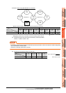
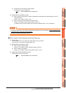
• In the case of CC-Link Ver.2 (Device names to be refreshed automatically are indicated as X, Y, and D.)
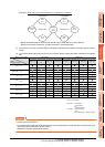
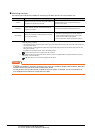
• In the case of CC-Link Ver.1 (Device names to be refreshed automatically are indicated as X, Y, and D.)
Monitor target Monitoring by cyclic transmission Monitoring by transient transmission
Master station (Remote network Ver.2 mode)
Local station Station No.1 (Ver.1 compatible)
Local station Station No.6 (Ver.2 compatible)
*1
Device name on PLC CPU
Automatic
refresh
Device name on master
station
Link
scan
GT Designer3 settings
Device name Set device range
Input X ← Remote input RX ← XX0 to X1FFF
Output Y → Remote output RY → YY0 to Y1FFF
Register (write area) D ←
Remote register
(write area)
RWw ← Ww Ww0 to Ww7FF
Register (read area) D →
Remote register
(read area)
RWr → Wr Wr0 to Wr7FF
Device name on PLC CPU
Automatic
refresh
Device name on master
station
Link
scan
GT Designer3 settings
Device name Set device range
Input X ← Remote input RX ← X X0 to X7FF
Output Y → Remote output RY → Y Y0 to Y7FF
Register (write area) D ←
Remote register
(write area)
RWw ← Ww Ww0 to WwFF
Register (read area) D →
Remote register
(read area)
RWr → Wr Wr0 to WrFF