


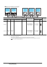
5 - 32
5. BUS CONNECTION
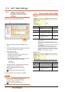
5.3 GOT Side Settings
POINTPOINTPOINT
When connecting to motion controller CPU (Q Series)
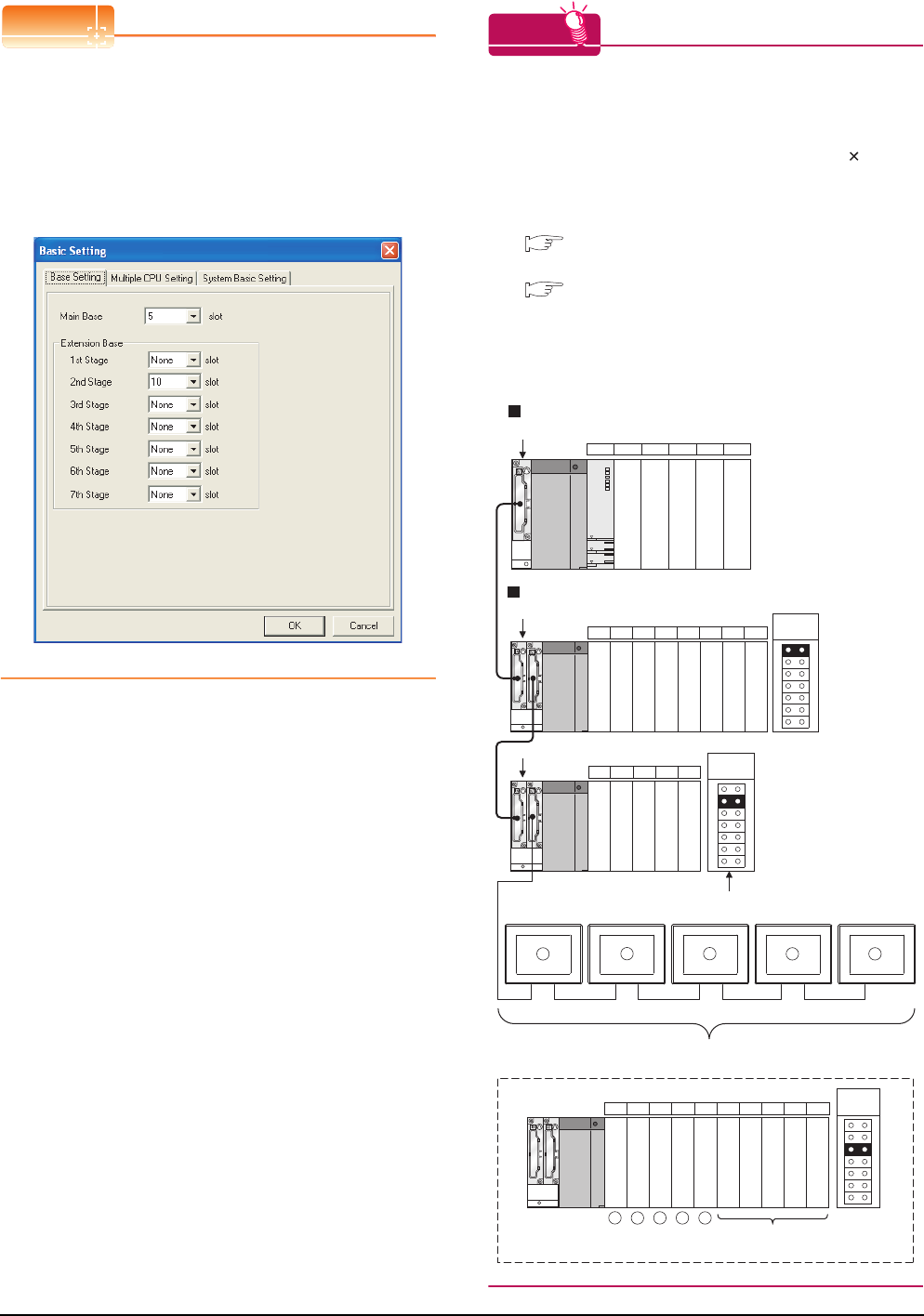
In the [Base Setting] on MT Developer, set "10" to the
number of slots for the extension base used for GOT
connection.
HINTHINTHINT
Setting unused I/O slots to empty (0 points) (only when
connecting to QCPU (Q mode))
Setting unused I/O slots as empty slots (0 points) from
"PC parameters" "I/O assignments" of GX Developer
allows you to use I/O numbers of "16 points number
of empty slots" for other purposes.
For details on I/O assignment settings, refer to the
following manual:
QnU User's Manual (Function Explanation,
Program Fundamentals)
Qn(H)/QnPH/QnPRHCPU User's Manual
(Function Explanation, Program Fundamentals)
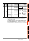
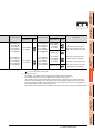
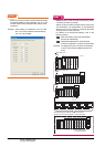
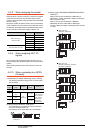
Example: When setting "2" to Stage No. and "0" to Slot
No. in the communication interface settings,
set "10" to [2nd Stage].
Example: I/O assignment (when 16 points are assigned
to each of all modules installed with the PLC
CPU)
Q35B
Q68B
01CPU 2 3 4
· · · · Slot No.
56789101112
Q65B
13 14 15 16 17
X00 to X0F
X10 to X1F
X20 to X2F
X30 to X3F
X40 to X4F
X60 to X6F
X70 to X7F
X80 to X8F
X90 to X9F
X50 to X5F
XA0 to XAF
XB0 to XBF
XC0 to XCF
XE0 to XEF
XF0 to XFF
X100 to X10F
X110 to X11F
XD0 to XDF
18 19 20 21 22 23 24 25 26 27
Schematic image of Stage No. for GOT connection
viewed from PLC CPU (16 points x 10 slots occupied)
X120 to X12F
X170 to X17F
X130 to X13F
X140 to X14F
X150 to X15F
X160 to X16F
X180 to X18F
X190 to X19F
X1A0 to X1AF
X1B0 to X1BF
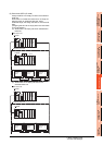
Set Empty (0 points)
to unused I/O slots.
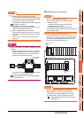
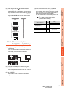
Main base unit
Extension base unit
Extension
stage 1
Extension
stage 2
Extension
stage 3
Stage No. setting
connector
1
1
2
2
3
3
4
4
5
5