22. FA TRANSPARENT FUNCTION
22.6 Personal Computer Side Setting
22 - 51
17
ROBOT
CONTROLLER
CONNECTION
18
CNC CONNECTION
19
GOT MULTI-DROP
CONNECTION
20
MULTIPLE-GT14, GT12,
GT11, GT10
CONNECTION FUNCTION
21
MULTI-CHANNEL
FUNCTION
22
FA TRANSPARENT
FUNCTION
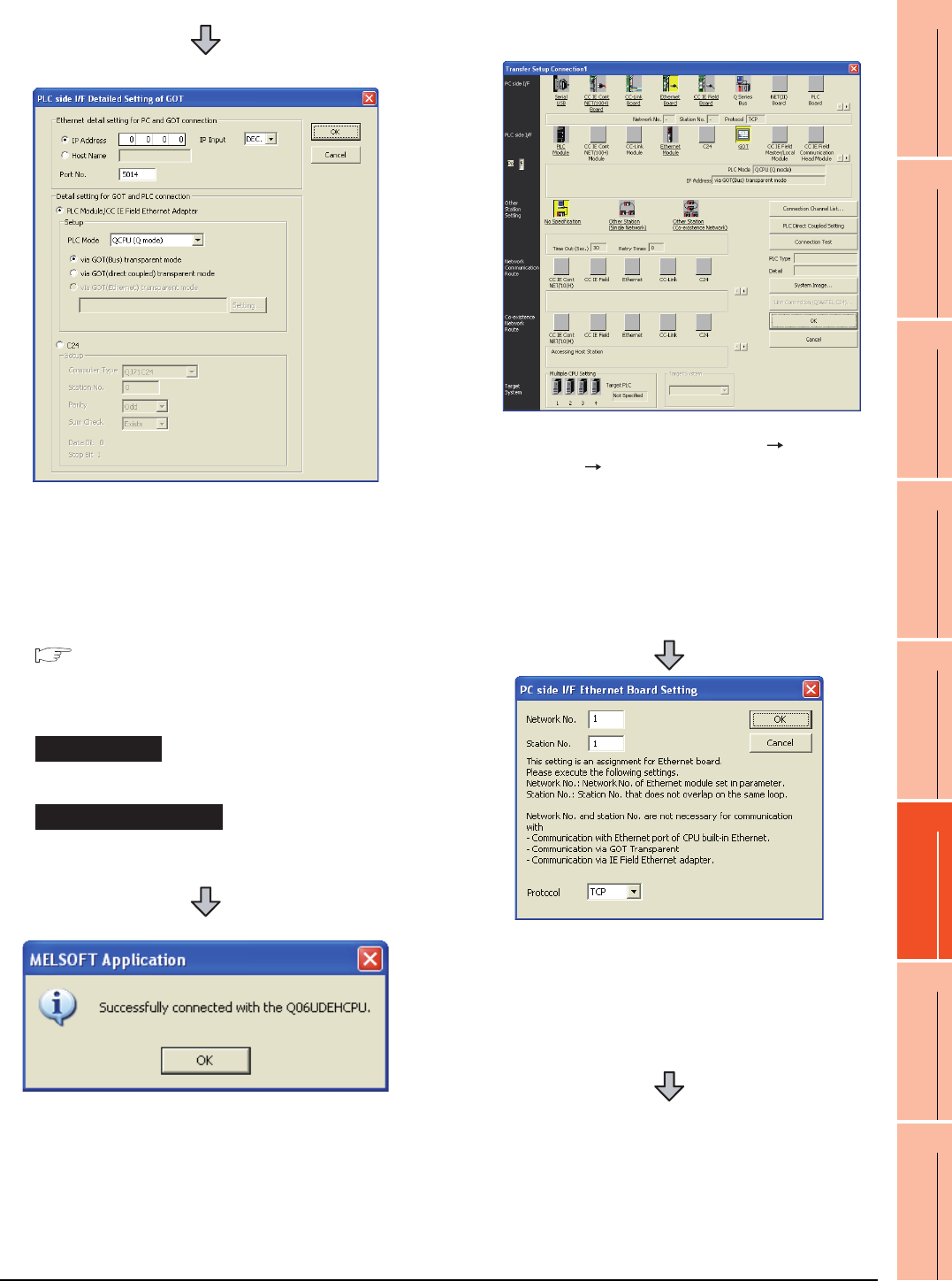
(2) Connecting the GOT and PLC in computer link
connection (when connecting to QJ71C24 (N))
(For bus connection)
6. Double-click [GOT] of the PLC side I/F to display
[PLC side I/F Detailed Setting of GOT].
7. Set the IP address and port No. in [Ethernet detail
setting for PC and GOT connection].
Set the IP address and port No. to the same as the
Ethernet download setting.
22.5.1 (b) Ethernet download setting
8. Check either of the followings in [Detail setting for
GOT and PLC connection].
[via GOT(Bus) transparent mode]
Mark the [via GOT(direct coupled) transparent mode]
checkbox.
9. The screen returns to [Transfer Setup]. Click
[Connection Test] to check if GX Developer has been
connected to the QCPU (Q mode).
1. Click the Connection Destination view [Connection
Destination] [(Connection target data name)] in the
Navigation window of GX Works2.
2. The [Transfer Setup] is displayed.
3. Set the [Transfer Setup]:
PC side I/F : Ethernet Board
PLC side I/F : GOT
Other Station Setting : No specification
4. Double-click [Ethernet Board] of the PC side I/F to
display [PC side I/F Ethernet Board Setting].
5. Set the protocol to TCP. Network No. and Station No.
are not required to be changed (default) because they
are not used.


