


21 - 18
21. MULTI-CHANNEL FUNCTION
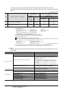
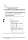
21.3 GOT Side Settings
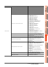
The number of channels and the functions that can be used differ depending on the GOT to be used.
The table below shows the allowable combinations of connection types, the number of channels and restricted
functions.
: Allowed : Restricted
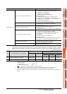
*1 When the functions below are used, the connectable number of channels may be restricted depending on the combination of the
functions to be used.
Fingerprint authentication Barcode function RFID function
Remote personal computer operation Video display function Operation panel function
External I/O function RGB display function Report function
Hard copy function(for printer output) Sound output function
Functions with the CF card unit or CF card extension unit
The video display function and RGB display function cannot be used together.
The CF card unit and the CF card extension unit cannot be used at the same time.
For details, refer to the following.
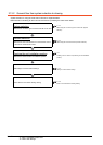
21.3.4 Determining the GOT side interface (Interface selection)
*2 When any of the connection methods below is used, Ethernet connection cannot be used although Ethernet download, gateway
function, MES interface function and file transfer function (FTP client) can be used.
Bus connection MELSECTNET/H connection
MELSECNET/10 connection CC-Link IE Controller Network connection
CC-Link connection MODBUS
®
/TCP connection CC-Link IE Field Network connection
*3 For the FA transparent function via the RS-232 connection, the RS-232 interface built in the GOT is available only.
When the RS-232 interface built in the GOT is already used, the FA transparent function is not available.
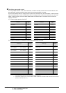
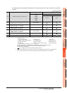
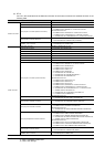
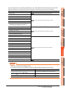
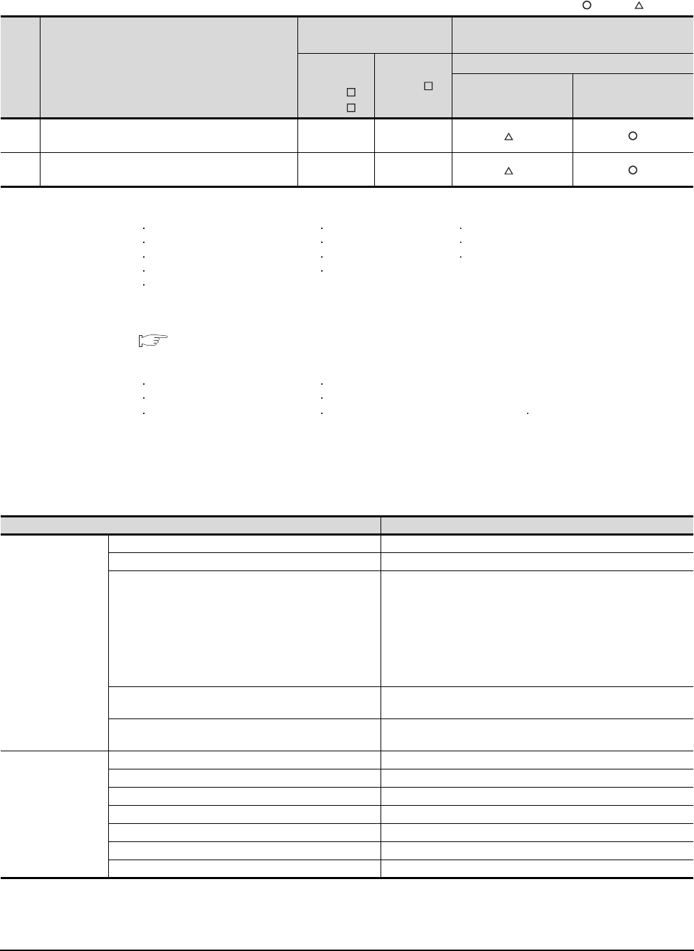
(3) GT14
For GT14, the combinations of the Ethernet connection and the serial connection are available as shown in the
following table.
(Continued to next page)
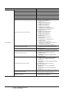
Item Allowable combination of connection types
GOT to be used
Functions that are restricted by the connection
type
*1*2
GT1595
GT1585
GT157
GT156
GT155
FA transparent function
RS-232 USB
(a)
• Bus/network/Ethernet connection: 1 channel
• Serial connection: 1 to 3 channels
Max. 4
channels
Max. 2
channels
*3
(b) • Serial connection: 4 channels
Max. 4
channels
Max. 2
channels
*3
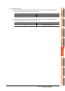
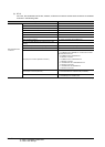
Connection type Reference
Ethernet connection
Ethernet connection 8.ETHERNET CONNECTION
CNC connection (Ethernet connection) 18.2.4Ethernet connection
Third party PLC connection (Ethernet connection)
Non-Mitsubishi Products 1
• 3. CONNECTION TO OMRON PLC 3.3 Ethernet Connection
Non-Mitsubishi Products 2
• 6. CONNECTION TO YASKAWA PLC 6.3 Ethernet Connection
• 7. CONNECTION TO YOKOGAWA PLC 7.3 Ethernet Connection
• 10. CONNECTION TO ALLEN-BRADLEY PLC 10.3 Ethernet
Connection
• 14. CONNECTION TO SIEMENS PLC 14.3 Ethernet Connection
Microcomputer connection (Ethernet)
Microcomputer, MODBUS Products, Peripherals
• 3. MICROCOMPUTER CONNECTION (ETHERNET)
MODBUS
®
/TCP connection
Microcomputer, MODBUS Products, Peripherals
• 5. MODBUS(R)/TCP CONNECTION
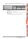
Serial connection
Direct CPU connection 6.DIRECT CONNECTION TO CPU
Computer link connection 7.COMPUTER LINK CONNECTION
CC-Link connection (via G4) 14.CC-Link CONNECTION (Via G4)
Inverter connection 15.INVERTER CONNECTION
Servo amplifier connection 16.SERVO AMPLIFIER CONNECTION
CNC connection (serial connection) 18.2.1Direct connection to CPU
GOT Multi- Drop Connection 19.GOT MULTI-DROP CONNECTION