


20. MULTIPLE-GT14, GT12, GT11, GT10 CONNECTION FUNCTION
20.3 Connection Diagram
20 - 5
17
ROBOT
CONTROLLER
CONNECTION
18
CNC CONNECTION
19
GOT MULTI-DROP
CONNECTION
20
MULTIPLE-GT14, GT12,
GT11, GT10
CONNECTION FUNCTION
21
MULTI-CHANNEL
FUNCTION
22
FA TRANSPARENT
FUNCTION
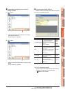
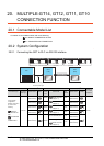
20.3 Connection Diagram
The following diagram shows the connection between the
GOT and the PLC.
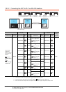
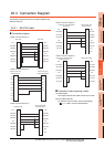
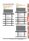
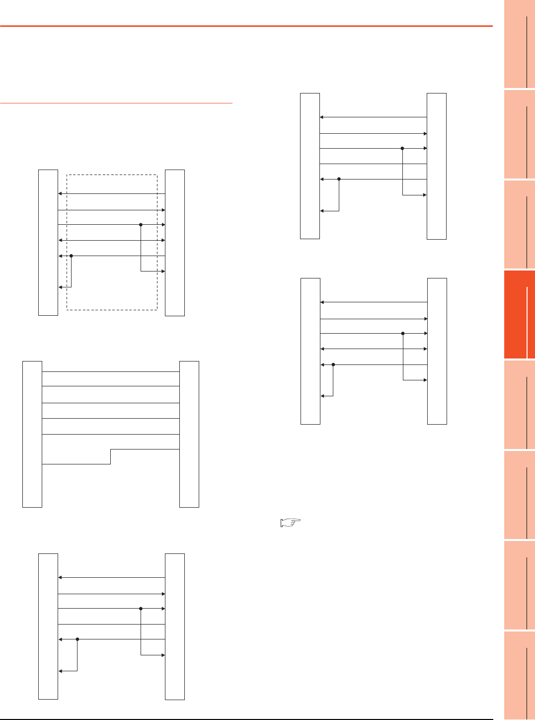
20.3.1 RS-232 Cable
Connection diagram
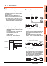
Precautions when preparing a cable
(1) Cable length
The length of the RS-232 cable must be 15m or less.
(2) GOT side connector
For the GOT side connector, refer to the following.
1.4.1 GOT connector specifications
RS232 connection diagram 1)
RS232 connection diagram 2)
RS232 connection diagram 3)
GOT side
GOT side
N.C.
RD(RXD)
SD(TXD)
ER(DTR)
SG
DR(DSR)
RS(RTS)
CS(CTS)
-
1
2
3
4
5
6
7
8
9
1
3
2
6
5
4
8
7
-
N.C.
SD(TXD)
RD(RXD)
DR(DSR)
SG
ER(DTR)
CS(CTS)
RS(RTS)
-
Second GOT side
(terminal block)
Brown
Red
Blue
Yellow
Green
Purple
Untied wire color
of GT10-C30R2-6P
SD
RD
ER
DR
SG
RS
CS
NC
NC
First GOT side
Second GOT side
(terminal block)
N.C.
RD(RXD)
SD(TXD)
ER(DTR)
SG
DR(DSR)
RS(RTS)
CS(CTS)
-
1
2
3
4
5
6
7
8
9
6
1
2
4
5
3
7
8
9
RS
SD(TXD)
RD(RXD)
DR(DSR)
SG
ER(DTR)
CS(CTS)
N.C.
N.C.
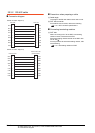
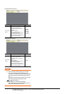
RS232 connection diagram 4)
RS232 connection diagram 5)
Second GOT side
(terminal block)
Cable (GT10-C02H-6PT9P)
D-Sub 9-pin
N.C.
RD (RXD)
SD (TXD)
ER (DTR)
SG
DR (DSR)
RS (RTS)
CS (CTS)
-
1
2
3
4
5
6
7
8
9
6
1
2
4
5
3
7
8
9
RS
SD (TXD)
RD (RXD)
DR (DSR)
SG
ER (DTR)
CS (CTS)
N.C.
N.C.
Cable (GT10-C02H-6PT9P)
D-Sub 9-pin side
Second GOT side
N.C.
RD (RXD)
SD (TXD)
ER (DTR)
SG
DR (DSR)
RS (RTS)
CS (CTS)
-
1
2
3
4
5
6
7
8
9
1
3
2
6
5
4
8
7
-
N.C.
SD (TXD)
RD (RXD)
DR (DSR)
SG
ER (DTR)
CS (CTS)
RS (RTS)
-