


11. CC-Link IE CONTROLLER NETWORK CONNECTION
11.3 GOT side settings
11 - 9
9
MELSECNET/H
CONNECTION (PLC
TO PLC NETWORK)
10
MELSECNET/10
CONNECTION (PLC
TO PLC NETWORK)
11
CC-Link IE CONTROLLER
NETWORK
CONNECTION
12
CC-Link IE FIELD
NETWORK
CONNECTION
13
CC-Link CONNECTION
(INTELLIGENT DEVICE
STATION)
14
CC-Link
CONNECTION
(Via G4)
15
INVERTER
CONNECTION
16
SERVO AMPLIFIER
CONNECTION
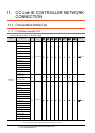
*1 For details, refer to the following manual.
CC-Link IE Controller Network Reference Manual
*2 This range is effective when collecting a large amount of
data (such as logging and recipe function) on other than the
monitor screen.
However, the range may affect the sequence scan time
when connecting to Q00UJ/Q00U/Q01U/Q02UCPU or Q00J/
Q00/Q01CPU.
If you want to avoid the influence on the sequence scan time,
do not set [High].
(This setting hardly affects QCPUs other than the above.)
*3 Set this range if you want to avoid the influence on the
sequence scan time further than the [Normal] setting when
connecting to Q00UJ/Q00U/Q01U/Q02UCPU or Q00J/Q00/
Q01CPU.
However, the monitor speed may be reduced.
*4 When the CC-Link IE Controller Network is in the extended
mode, set to [CC IE Control extended mode]. The extended
mode can be used in GT Designer3 version 1.22Y or later.
POINTPOINTPOINT
(1) Switch setting example
For the switch setting example, refer to the
following.
11.4 PLC Side Setting
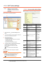
(2) Communication interface setting by Utility
The communication interface setting can be
changed on the Utility's [Communication Settings]
after writing [Communication Settings] of project
data.
For details on the Utility, refer to the following
manual.
GT User’s Manual
(3) Precedence in communication settings
When settings are made by GT Designer3 or the
Utility, the latest setting is effective.
(4) Network type
Be sure to set the same network types for the CPU
side and the GOT side. If the net work types of the
CPU side and the GOT side are different, an error
is displayed in the system alarm of the GOT side.
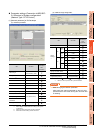
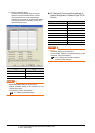
11.3.3 Routing parameter setting
Up to 64 [Transfer Network No.]s can be set.
However, the same transfer network number cannot be set
twice or more (multiple times).
Therefore, the one that can access to other station from the
request source host GOT is 64 kinds of [Transfer Network
No.]s.
POINTPOINTPOINT
Routing parameter setting
When communicating within the host network, routing
parameter setting is unnecessary.
For details of routing parameters, refer to the following
manual.
CC-Link IE Controller Network
Reference Manual
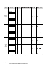
*1 Basic model QCPU and the QSCPU are not included.
POINTPOINTPOINT
(1) Routing parameter setting of relay station
Routing parameter setting is also necessary for
the relay station.
For the setting, refer to the following.
11.4 PLC Side Setting
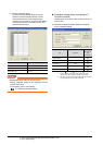
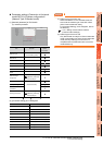
(2) Parameter reflection function of MELSOFT Navigator
(a) The color of the cells for the items which are
reflected to GT Designer3 from MELSOFT
Navigator changes to green. Set items, which
are displayed in green cells, from the
MELSOFT Navigator.
(b) When the settings of Transfer network No.,
Relay network No. or Relay station No. are
reflected to the parameter from the MELSOFT
Navigator, those settings are added. Items set
in advance are not deleted.However, if the
target network No. overlaps, the item set in
advance is overwritten.
(c) The routing information is used manually by
the user when the data is created. Therefore,
after changing the network configuration by
MELSOFT Navigator, create a routing
information again. For details of the creation
of the routing information, refer to the
MELSOFT Navigator help.
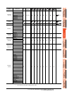
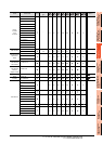
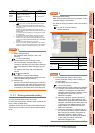
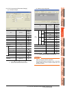
Monitor
Speed
Set the monitor speed for the CC-
Link IE controller network.
This setting is not valid in all
systems.
(Default: High)
High
*2
/Normal/Low
*3
Item Description Range
Item Range
Transfer Network No. 1 to 239
Relay Network No. 1 to 239
Relay Station
No.
Universal model QCPU 1 to 120
QCPU other than Universal model
QCPU
*1
1 to 64