


15 - 46
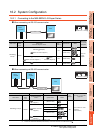
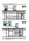
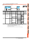
15. INVERTER CONNECTION
15.6 Device Range that Can Be Set
POINTPOINTPOINT
(1) Monitoring Pr.37
GOT cannot monitor the parameter (Pr.37) of
FREQROL-E500/S500(E)/F500J/D700/F700PJ/
E700.
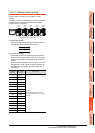
(2) When setting "8888" or "9999" to inverter parameter (Pr)
"8888" and "9999" designate special function.
To set these numbers from GOT, designate a
number as shown below.
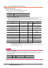
(3) Precautions for setting calibration parameter
(Pr900 to Pr905)
When setting a calibration parameter (Pr900 to
Pr905), it is necessary to set the value below for
extension second parameter (SP108), depending on
the device number to be used and the inverter model.
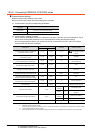
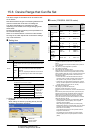
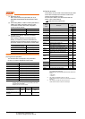
(5) Programmed operation
The devices below correspond to the parameters
(Pr.201 to Pr.230) of FREQROL-A500 series.
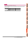
*1 To set the start time (PG10 to PG19, PG40 to PG49, PG70
to PG79), set hour or minute in the upper 8bits, and minute
or second in the lower 8bits.
Example) To set 13 hour 35 minute
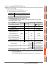
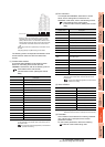
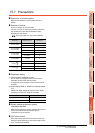
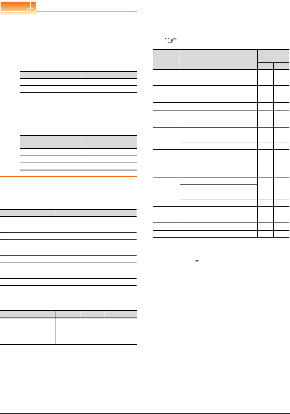
(6) Special parameter
The numbers of the inverter’s virtual devices (SP) used
for the GOT correspond to instruction codes of the
inverter communication function.
For instruction details, and values to be read and
written, refer to the following,
Manual of the inverter used
*1 GOT cannot monitor SP109 to SP111 if the conditions below
are satisfied at the same time.
(Only FREQROL-E500/S500(E)/F500J/D700/F700PJ/E700
series)
•Pr37 0
• SP127 = 1
*2 Only reading is possible for SP111 to SP114.
These devices cannot be used for a write object (numerical
input etc.).
*3 Only writing is possible for SP124 and SP125.
These devices cannot be used for read object.
Set value of inverter side Value specified by GOT
8888 65520
9999 65535
Value to be set to extension
second parameter (SP108)
Description
H00 Offset/gain
H01 Analog
H02 Analog value at terminal
Device name Description
PG0 to PG9 Program set 1 (running frequency)
PG10 to PG19
*1
Program set 1 (time)
PG20 to PG29 Program set 1 (rotation direction)
PG30 to PG39 Program set 2 (running frequency)
PG40 to PG49
*1
Program set 2 (time)
PG50 to PG59 Program set 2 (rotation direction)
PG60 to PG69 Program set 3 (running frequency)
PG70 to PG79
*1
Program set 3 (time)
PG80 to PG89 Program set 3 (rotation direction)
Time to be set 13H 35M Remark
Convert "hour" and "minute"
into hexadecimal.
H0D H23 HEX
Combine upper and lower 8-
bit values.
Input H0D23 or 3363. -
Device
name
Description
Instruction
code
Read Write
SP108 Second parameter changing 6C
H ECH
SP109
*1
Set frequency (RAM) 6DH EDH
SP110
*1
Set frequency (RAM, E
2
PROM)
6E
H EEH
SP111
*1*2
Output frequency 6FH -
SP112
*2
Output current 70H -
SP113
*2
Output voltage 71H -
SP114
*2
Special monitor 72H -
SP115 Special monitor selection No. 73
H F3H
SP116
Alarm definition all clear - F4
H
Latest alarm, second alarm in past 74H -
SP117 Third alarm in past, fourth alarm in past 75
H -
SP118 Fifth alarm in past, sixth alarm in past 76
H -
SP119
Seventh alarm in past, eights alarm in
past
77
H -
SP121
Inverter status monitor (extended)
79
H F9H
Run command (extend)
SP122
Inverter status monitor 7A
H -
Run command - FA
H
SP123 Communication mode 7BH FBH
SP124
*3
All parameter clear - FCH
SP125
*3
Inverter reset - FDH
SP127 Link parameter extended setting 7FH FFH