


7 - 24
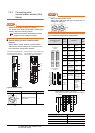
7. COMPUTER LINK CONNECTION
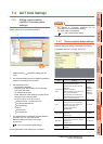
7.5 PLC Side Setting
7.5.2 Connecting serial
communication module (QnA
Series)
POINTPOINTPOINT
Serial communication module (QnA Series)
For details of the serial communication module (QnA
Series), refer to the following manual.
Serial Communication Module User's Manual
(Modem Function Additional Version)
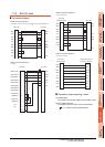
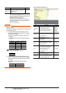
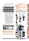
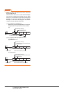
Switch setting on serial communication
module
Set the Station number switches, the Mode setting
switch for the channel used for GOT connection, and
the Transmission specifications switches.
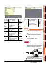
(1) Mode setting switch
*1 The mode switch in the figure is for the AJ71QC24 (N) (-R2/
R4).
POINTPOINTPOINT
When connecting a GOT to CH2
Set the CH1 side mode switch to any other than "0"
(interlocked operation).
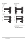
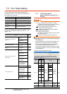
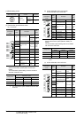
(2) Transmission specifications setting switch
*1 The following shows the layout of switches in the case of the
following hardware versions for the module.
Switch settings and switch ON/OFF directions are the same.
Mode setting switch
*1
Description Set value
Dedicated protocol (Format 5)
(Binary mode)
5
A
J71QC24N
RUN
CPUR/W
NEU
ACK
NAK
C/N
P/S
PRO
SIO
SD.WAIT
SD
RD
CH1.ERR.
CH2.ERR.
NEU
ACK
NAK
C/N
P/S
PRO
SIO
SD.WAIT
SD
RD
CH.1 CH.2
1
CH1 CH2
STATION
No.
MODE
SW
01
02
03
04
05
06
07
08
09
10
11
12
RDA
RDB
SG
SDA
SDB
NC
FG
CH1
RS-232C
CH2
RS422
RS485
8
4
0
C
8
4
0
C
5
0
5
0
10
AJ71QC24N, AJ71QC24N-R2,
AJ71QC24N-R4,AJ71QC24,
AJ71QC24-R2, AJ71QC24-R4
(3)
(1)
(2)
A
1SJ71QC24N
CH1
ERR.
C/N
P/S
PRO
SID
CH2
ERROR
RD
SW.E
NEU
ACK
NAK
SD.W.
SD
STS ERR.
DISPLAY
5
0
5
0
CH1 CH2
10 1
STATION NO.
MODE
A1SJ71QC24N
RUN
RD
C.R/W
NEU
ACK
NAK
SD.W.
SD
ERR.
C/N
P/S
PRO
SIO
AB
CH1 RS-232-C
CH2 RS-422/RS-485
SG
(FG)
(NC)
SDA
SDB
RDA
RDB
8
4
0
C
8
4
0
C
ON
2
1
4
3
6
5
8
7
10
9
12
11
SW
(1)
(3)
(2)
A1SJ71QC24N1, A1SJ71QC24N1-R2
A1SJ71QC24N, A1SJ71QC24N-R2,
A1SJ71QC24, A1SJ71QC24-R2
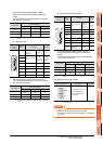
MODE
CH
Transmission
specifications setting
switch
Setting
switch
Description
Set
value
AJ71QC24(N)
(-R2/R4)
A1SJ71QC24(N)
(N1)(-R2)
*1
SW01
Operation
setting
Independent
operation
OFF
SW02
Data bit
setting
8bits ON
SW03
Parity bit
enable/disable
setting
Enable ON
SW04
Even/odd parity
setting
Odd OFF
SW05 Stop bit setting 1bit OFF
SW06
Sum check
enable/disable
setting
Enable ON
SW07
Write during
RUN enable/
disable setting
Enable ON
SW08
Setting change
enable/disable
Disable
(prohibit)
OFF
SW09
to
SW12
Transmission
speed setting
(Consistent
with the GOT
side
specifications)
See (a)
SW13
to
SW15
―
The switch is
located on
the left side
of the
module.
(only on
AJ71QC24 (-
R2/R4))
All OFF
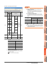
Target unit Hardware version
A1SJ71QC24 Version E hardware or earlier
A1SJ71QC24-R2 Version D hardware or earlier
A1SJ71QC24N, A1SJ71QC24N-R2 Version A hardware
MODE
CH2CH1
SW
01
02
03
04
05
06
07
08
09
10
11
12
ONON
ON
2
1
4
3
6
5
8
7
10
9
12
11
SW
1
8
2
3
4
5
6
7
9
10
11
12
SW
CH1/2
ON