


3 - 20
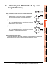
3. ACCESS RANGE FOR MONITORING
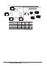
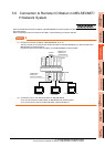
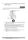
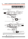
3.6 Connection to Remote I/O Station in MELSECNET/H Network System
Direct CPU connection
(1) The network units (QJ72LP25-25, QJ72LP25G, QP72BR15) of the remote I/O station are handled as PLC CPU.
Connect the GOT to the RS-232 interface of the network unit.
For cables required for connection with the network module and other details, refer to the following.
6. DIRECT CONNECTION TO CPU
(2) Specify a type including MELSEC-Q (including multiple), or MELSEC-QnU for the controller type on GT
Designer3. Then, specify [[NW No.] (Network No. of the remote I/O network) to 1, and specify [Station No.]
(Master station) to 0.] as the monitoring target in the network setting of the device setting dialog box. (GT16,
GT15 only)
The GOT monitors stations on the MELSECNET/H network with the transient transmission.
Therefore, a longer time-lag occurs for displaying objects compared with directly monitoring the PLC CPU.
For displaying objects with a shorter time-lag, execute the cyclic transmission so that the GOT can monitor link
devices B and W of the host station set in the MELSECNET/H network.
For settings required for the PLC CPU, refer to the following manual.
Q Corresponding MELSECNET/H Network System Reference Manual (Remote I/Q network)
(3) To monitor other networks, set the routing parameter to the PLC CPU as necessary. For routing parameter
settings of the PLC CPU, refer to the following manual.
Q corresponding MELSECNET/H Network System Reference Manual (PLC to PLC network)
Computer link connection
(1) Connect the GOT to the serial communication module (QJ71C24, QJ71C24-R2, QJ71C24N, QJ71C24N-R2,
QJ71C24N-R4) or modem interface module (QJ71CMO) mounted on the remote I/O station.
For the cables required for connection with the serial communication module or modem interface module and
other details, refer to the following.
7. COMPUTER LINK CONNECTION
(2) Specify a type including MELSEC-Q (including multiple), or MELSEC-QnU for the controller type on GT
Designer3. Then, specify [[NW No.] (Network No. of the remote I/O network) to 1, and specify [Station No.]
(Master station) to 0.] as the monitoring target in the network setting of the device setting dialog box. (GT16,
GT15 only)
The GOT monitors stations on the MELSECNET/H network with the transient transmission.
Therefore, a longer time-lag occurs for displaying objects compared with directly monitoring the PLC CPU.
For displaying objects with a shorter time-lag, execute the cyclic transmission so that the GOT can monitor link
devices B and W of the host station set in the MELSECNET/H network.
For settings required for the PLC CPU, refer to the following manual.
Q Corresponding MELSECNET/H Network System Reference Manual (Remote I/Q network)
(3) To monitor other networks, set the routing parameter to the PLC CPU as necessary. For routing parameter
settings of the PLC CPU, refer to the following manual.
Q corresponding MELSECNET/H Network System Reference Manual (PLC to PLC network)