


16 - 18
16. SERVO AMPLIFIER CONNECTION
16.6 Device Range that Can Be Set
POINTPOINTPOINT
Monitoring servo amplifier
Carefully read the manual of servo amplifier to be
connected and fully understand the operating
procedures before monitoring.
Before operation, check the parameter settings.
Improper settings may cause some machines to
perform unexpected operation.
The parameter settings must not be changed
excessively. Operation will be insatiable.
(1) Parameters with * in front of it's abbreviated name
For the parameter with * in front of it's abbreviated
name, powering off the servo amplifier after setting
then on makes the parameter valid.
(2) Data length for setting virtual devices for servo
amplifier
Set the following data length for setting devices.
• PRM, ST, AL, PA, PB, PC, PD, POS, SPD, ACT,
DCT, DWL, AUX
: 16bits or 32bits (depends on the data of servo
amplifier)
• DI, DO, TMI, TMO, TMD: 32bits
If the above data length was not set, data would
not be set to the servo amplifier correctly or the
GOT can not monitor normally.
(a) Monitoring
• When the 16-bit data is handled as 32-bit
data, the upper 16bits are displayed as 0.
• When the 32-bit data is handled as 16-bit
data, the lower 16bits only are displayed as
0.
(b) Writing
The GOT writes within the range of data
length set. Note that the servo amplifier
responds correctly while the written data is
invalid in the servo amplifier side when the
written data is outside the range of values
which can be set by the servo amplifier.
(3) Memory area for writing parameters
Parameters are written to RAM or E
2
PROM of
servo amplifier.
(a) When written to RAM
Remember that written parameters are
cleared when power supply to the servo
amplifier is turned off.
(b) When written to E
2
PROM
Written parameters are not cleared even
when power supply to the servo amplifier is
turned off.However, there are limits in the
number of writing to E
2
PROM.
If the data is frequently updated (more than
once in an hour), write the parameters to the
RAM.
For details, refer to the manual of the servo
amplifier used.
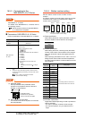
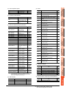
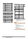
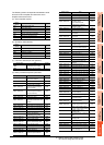
(2) MELSERVO-J2M-P8A
*1 Use PRM0 to PRM29 when writing parameters to the servo
amplifier RAM.
PRM1000 to PRM1029 are used when writing parameters to
E
2
PROM of the servo amplifier.
*2 The GOT cannot read or write data from/to consecutive
devices.
*3 Only reading is possible.
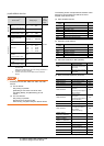
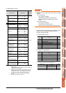
POINTPOINTPOINT
Precautions for SP, OM, and TMO devices
(1) For bit devices
Only writing is possible.
[Alternate] of a bit switch cannot be used.
Use [Set], [Reset], and [Momentary] of a bit
switch.
(2) For word devices
Only writing is possible.
Numerical input cannot be used.
When writing, use [Word Set] of a data set switch.
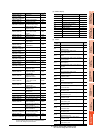
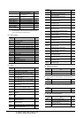
Device name
*2
Setting range available
Device
No.
represent
ation
Bit device
Servo amplifier request
(SP)
SP1 to SP2
Decimal
Operation mode selection
(OM)
OM0 to OM4
Word device
Basic parameter
Expansion parameter
(PRM)
*1
PRM0 to PRM29
PRM1000 to PRM1029
Status display (ST) ST0 to ST2
Alarm (AL)
AL0
AL11 to AL13
AL200 to AL205
AL210 to AL215
AL230 to AL235
External input (DI)
*3
DI0 to DI2
External output (DO) DO0 to DO1
Forced output of signal pin
(for test operation)
(TMO)
TMO0