


4 - 28
4. HOW TO MONITOR REDUNTANT SYSTEM
4.8 Connection to the Redundant Type Extension Base Unit
4.8.4 CC-Link connection (Via G4) (Connection to the CC-Link module mounted
on redundant type extension base unit)
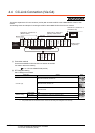
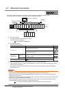
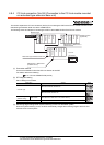
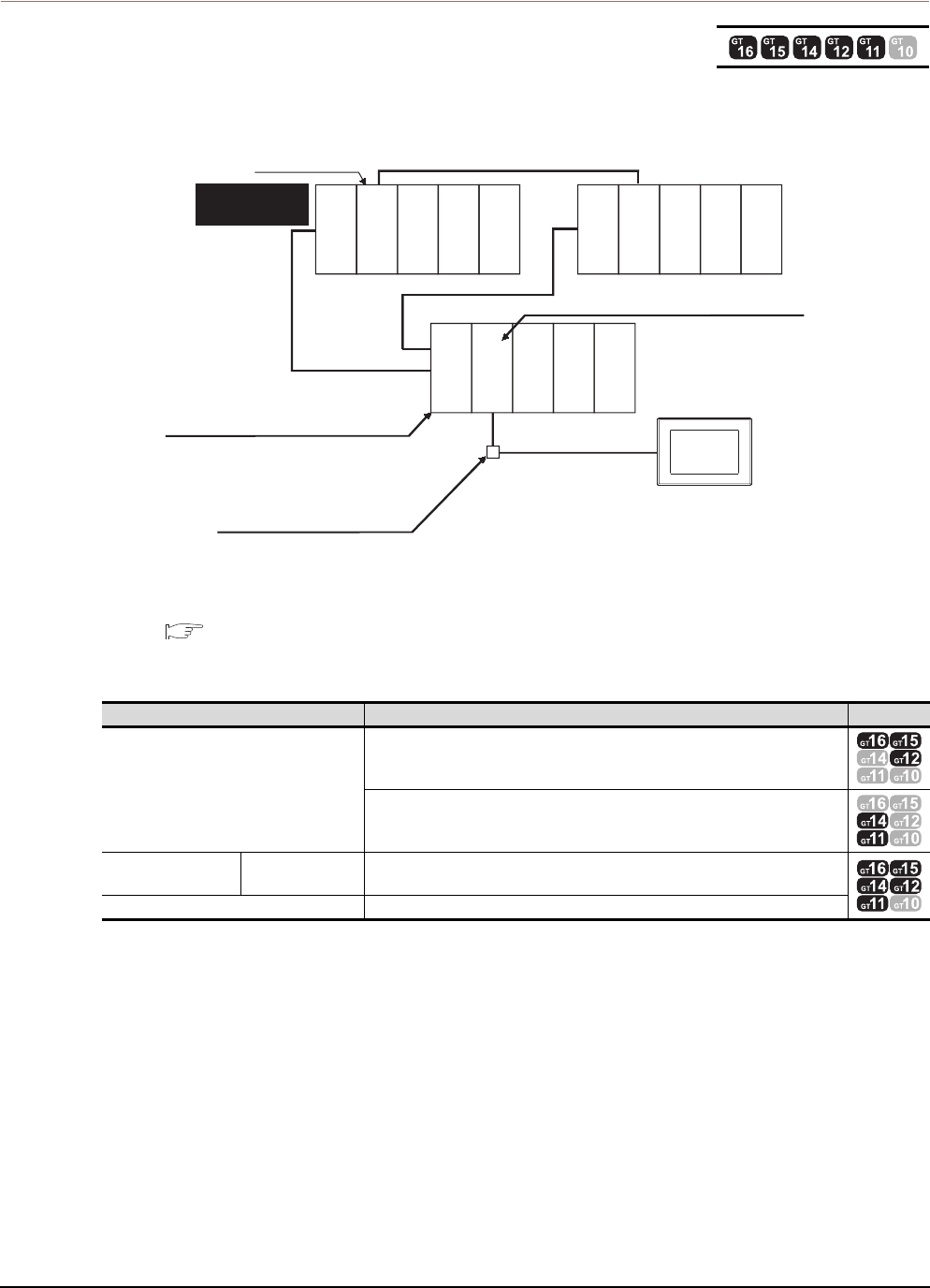
This section explains the CC-Link connection (Via G4) for connecting the GOT to the CC-Link module mounted on the
redundant type extension base unit via the AJ65BT-G4-S3.
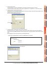
The following shows an example of connecting the GOT to the AJ65BT-G4-S3 of the CC-Link network.
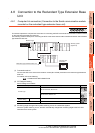
(1) Connection method
Connect the AJ65BT-G4-S3 of the CC-Link network to the GOT.
For details, refer to the following.
14. CC-Link CONNECTION (Via G4)
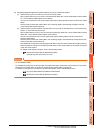
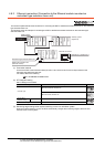
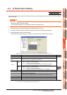
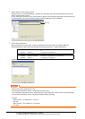
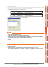
(2) GT Designer3 setting
Set GT Designer3 as follows.
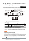
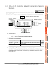
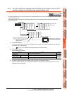
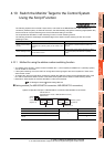
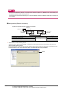
(3) Monitoring target change when system switching occurs in a redundant system
When the system switching occurs, the GOT automatically changes the monitoring target to the PLC CPU
switched to the control system.
Setting item Settings Model
Controller Type
MELSEC-QnA/Q/QS, MELDAS C6*
MELSEC-QnA/Q, MELDAS C6*
Device setting
(Network setting)
Master station Other (NW No.0, Station No.0 or FF (master station))
Q Redundant Setting Do not set the item.
Monitor target
Control system
(System A)
GOT
Standby system
(System B)
Power supply
module
Power supply
module
Power supply
module
Q25PRHCPU
QJ61BT11N
Q25PRHCPU
QJ71BR11
QJ71BR11
Empty
Empty
Empty
Empty
Empty
Empty
Empty
CC-Link
connection
Redundant type extension base unit
Network No. 0, Station No. 1
(AJ65BT-G4-S3)
Network No. 0, Station No. 0
(Master station)