


1 - 14
1. PREPARATORY PROCEDURES FOR MONITORING
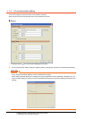
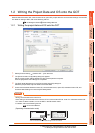
1.1 Setting the Communication Interface
POINTPOINTPOINT
Channel No., drivers, [RS232 Setting]
(1) Channel No.2 to No.4
Use the channel No.2 to No.4 when using the Multi-channel function.
For details of the Multi-channel function, refer to the following.
Mitsubishi Products 21. MULTI-CHANNEL FUNCTION
(2) Drivers
The displayed items for a driver differ according to the settings [Manufacturer], [Controller Type] and [I/F].
When the driver to be set is not displayed, confirm if [Manufacturer], [Controller Type] and [I/F] are correct.
[Setting the communication] section in each chapter
(3) [RS232 Setting] of GT14
Do not use [RS232 Setting] of GT14 for other than the 5V power feeding to the RS-232/485 signal conversion
adaptor.
For details, refer to the following manual.
GT14 User's Manual 7.11 RS-232/485 Signal Conversion Adaptor
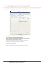
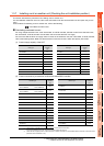
1.1.3 Precautions
(1) When using the multiple CPU system
When using the GOT to monitor the multiple CPU system of other stations, select [MELSEC-Q(Multi)/Q-Motion]
or [MELSEC-QnU, Q17nD/M/NC/DR, CRnD-700] for the type, regardless of the host PLC CPU type (QCPU,
QnACPU, ACPU). When other models are selected, the setting of the CPU No. becomes unavailable.
(2) Precautions for changing model
(a) When devices that cannot be converted are included.
When setting of [Manufacturer] or [Controller Type] is changed, GT Designer3 displays the device that
cannot be converted (no corresponding device type, or excessive setting ranges as [??]. In this case, set
the device again.
(b) When the changed Manufacturer or Controller Type does not correspond to the network.
The network will be set to the host station.
(c) When the Manufacturer or Controller Type is changed to [None]
The GT Designer3 displays the device of the changed channel No. as [??]. In this case, set the device
again.
Since the channel No. is retained, the objects can be reused in other channel No. in a batch by using the
[Device Bach Edit], [CH No. Batch Edit] or [Device List].
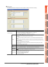
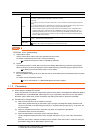
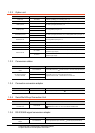
Item Description
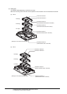
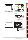
Extension I/F setting Set the communication unit attached to the extension interface of the GOT.
CH No.
Set the CH No. according to the intended purpose.
The number of channels differs depending on the GOT to be used.
0: Not used
1 to 4: Used for connecting a controller of channel No. 1 to 4 set in Setting connected equipment (Channel
setting)
5 to 7: Used for barcode function, RFID function, remote personal computer operation (serial), report function
(when using the serial printer) or hard copy function (when using the serial printer)
* : Used for remote personal computer operation (Ethernet), video display function, multimedia function,
operation panel function, external I/O function, RGB display function, report function (when using a
PictBridge compatible printer), hard copy function (when using a PictBridge compatible printer), sound
output function, functions with the CF card unit or CF card extension unit, Ethernet download, gateway
function or MES interface function
Driver
Set the driver for the device to be connected.
None Each driver for connected devices
Detail Setting
Make settings for the transmission speed and data length of the communication driver.
Refer to each chapter of the equipment to be connected to the GOT.