


16. SERVO AMPLIFIER CONNECTION
16.6 Device Range that Can Be Set
16 - 39
9
MELSECNET/H
CONNECTION (PLC
TO PLC NETWORK)
10
MELSECNET/10
CONNECTION (PLC
TO PLC NETWORK)
11
CC-Link IE CONTROLLER
NETWORK
CONNECTION
12
CC-Link IE FIELD
NETWORK
CONNECTION
13
CC-Link CONNECTION
(INTELLIGENT DEVICE
STATION)
14
CC-Link
CONNECTION
(Via G4)
15
INVERTER
CONNECTION
16
SERVO AMPLIFIER
CONNECTION
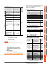
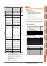
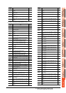
(9) MELSERVO-J4-*A
*1 Use 1 to 80 of PA, PB, PC, PD, PE, and PF when the GOT
writes data to RAM of the servo amplifier.
Use 1001 to 1080 of PA, PB, PC, PD, PE, and PF when the
GOT write data to E
2
PROM of the servo amplifier.
*2 The GOT cannot read or write data from/to consecutive
devices.
*3 Only reading is possible.
*4 Only reading is possible for DI0 to DI1.
POINTPOINTPOINT
Precautions for SP, OM, TMB, TMI, TMO, and TMD
devices
(1) For bit devices
Only writing is possible.
[Alternate] of a bit switch cannot be used.
Use [Set], [Reset], and [Momentary] of a bit
switch.
(2) For word devices
Only writing is possible.
Numerical input cannot be used.
When writing, use [Word Set] of a data set switch.
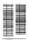
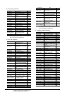
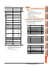
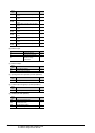
The following shows correspondences between virtual
devices for servo amplifier and data of the servo
amplifier used with the GOT.
(a) Servo amplifier request
(b) Operation mode selection
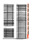
(c) Instruction demand (for test operation)
Device name
*2
Setting range
Device
No.
represen
tation
Bit device
Servo amplifier request (SP) SP0 to SP6
Decimal
Operation mode selection
(OM)
OM0 to OM4
Instruction demand
(for test operation) (TMB)
TMB1 to TMB6
Word device
Basic setting parameter
(PA)
*1
PA1 to PA32
PA1001 to PA1032
Gain
filter parameter
(PB)
*1
PB1 to PB64
PB1001 to PB1064
Extension setting
parameter (PC)
*1
PC1 to PC80
PC1001 to PC1080
I/O setting parameter
(PD)
*1
PD1 to PD48
PD1001 to PD1048
Extension setting 2
parameter (PE)
*1
PE1 to PE64
PE1001 to PE1064
Extension setting 3
parameter (PF)
*1
PF1 to PF48
PF1001 to PF1048
Status display (ST)
*3
ST0 to ST41
Alarm (AL)
*3
AL0 to AL1
AL11 to AL25
AL200 to AL205
AL210 to AL215
AL230 to AL235
Alarm (ALM)
*3
ALM0 to ALM1
ALM11 to ALM52
ALM200 to ALM215
ALM220 to ALM235
ALM240 to ALM255
External input (DI)
*4
DI0 to DI2
External output (DO)
*3
DO0 to DO1
Input signal for test operation
(for test operation) (TM0)
TMI0
Forced output of signal pin
(for test operation) (TMO)
TMO0
Set data
(for test operation) (TMD)
TMD0 to TMD1
TMD3
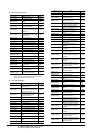
Device
name
Item Symbol
SP0 Status display data clear ―
SP1 Current alarm clear ―
SP2 Alarm history clear ―
SP3 External input signal prohibited ―
SP4 External output signal prohibited ―
SP5 External input signal resumed ―
SP6 External output signal resumed ―
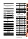
Device
name
Item Symbol
OM0 Normal mode (not test operation mode) ―
OM1 JOG operation ―
OM2 Positioning operation ―
OM3 Motorless operation ―
OM4 Output signal (DO) forced output ―
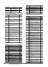
Device
name
Item Symbol
TMB1 Temporary stop command ―
TMB2
Test operation (positioning operation) start
command
―
TMB3 Forward rotation direction ―
TMB4 Reverse rotation direction ―
TMB5 Restart for remaining distance ―
TMB6 Remaining distance clear ―