


8. ETHERNET CONNECTION
8.4 PLC Side Setting
8 - 33
1
PREPARATORY
PROCEDURES FOR
MONITORING
2
DEVICE RANGE
THAT CAN BE SET
3
ACCESS RANGE
FOR MONITORING
4
HOW TO MONITOR
REDUNTANT
SYSTEM
5
BUS CONNECTION
6
DIRECT
CONNECTION TO
CPU
7
COMPUTER LINK
CONNECTION
8
ETHERNET
CONNECTION
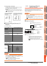
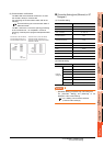
(3) Communication confirmation
The RDY LED on the Ethernet module turn on when
the module is ready to communicate.
For confirming the communication state, refer to the
following.
8.3.4 ■Confirming the communication state of
Ethernet module
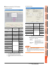
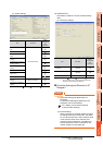
[Controller Setting] and [Ethernet] of GT
Designer3
(1) Controller setting
(2) Ethernet setting
POINTPOINTPOINT
[Controller Setting] and [Ethernet] of GT Designer3
For [Controller Setting] and [Ethernet] of GT
Designer3, refer to the following.
8.3.1 Setting communication interface
(Communication settings)
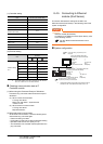
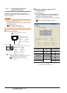
8.4.6 Connecting to Ethernet
module (A Series)
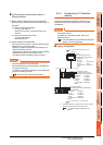
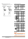
This section describes the settings of the GOT and
Ethernet module (A Series) in the following case of the
system configuration.
POINTPOINTPOINT
Ethernet module (A Series)
For details of the Ethernet module (A Series), refer to
the following manual.
For A Ethernet Interface Module User’s Manual
System configuration
*1 The Ethernet module is mounted on the base unit slot 0.
The Start I/O No. of the Ethernet module is set to "0".
*2 These setting items do not exist at the PLC side. However,
the virtual values must be set on the GOT side.
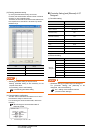
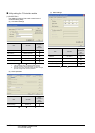
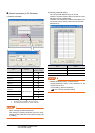
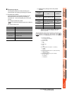
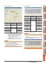
■ [Controller Setting] and [Ethernet] of GT Designer3
Item Set value (Use default value)
GOT NET No. 1
GOT PLC No. 1
GOT IP Address 192.168.0.18
GOT Port No.
(Communication)
5001
GOT Port No.
(Ethernet Download)
5014
Default Gateway 0.0.0.0
Subnet Mask 255.255.255.0
Retry 3times
Startup Time 3sec
Timeout Time 3sec
Delay Time 0ms
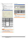
Item Set value
Ethernet
setting No.1
Host *
N/W No. 1
PLC No. 2
Type AJ71QE71
IP address 192.168.0.19
Port No. 5001 (fixed)
Communication UDP (fixed)
RUN BUF1
BUF2
BUF3
BUF4
BUF5
BUF6
BUF7
BUF8
RDY
BSY
SW.ERR.
COM.ERR.
CPU R/W
TEST
TEST ERR.
BSY
SW.ERR.
COM.ERR.
CPU R/W
TEST ERR.
TEST
RDY
RUN BUF1
BUF2
BUF3
BUF4
BUF5
BUF6
BUF7
BUF8
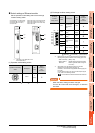
A1SJ71QE71N3-T, A1SJ71QE71N-B5,
A1SJ71QE71N-B2, A1SJ71QE71N-T,
A1SJ71QE71N-B5T,A1SJ71QE71-B5,
A1SJ71QE71-B2
AJ71QE71N3-T, AJ71QE71N-B5,
AJ71QE71N-B2, AJ71QE71N-T,
AJ71QE71N-B5T, AJ71QE71,
AJ71QE71-B5
<GOT> (The settings other than the
following are set to the default)
*2
*2
*1
Network No.
: 1
PLC No. : 1
IP address : 192.168.0.18
Port No. : 5001
Communication format: UDP (fixed)
Network No. : 1 (virtual)
PLC No. : 2 (virtual)
IP address : 192.168.0.19
Port No. : 5001
Communication format : UDP(fixed)
<Ethernet module> (The settings other than the
following are set to the default)
[Controller Setting] and [Ethernet] of GT
Designer3
■
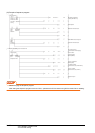
■ Switch settings of Ethernet module
■ Sequence program