22. FA TRANSPARENT FUNCTION
22.6 Personal Computer Side Setting
22 - 39
17
ROBOT
CONTROLLER
CONNECTION
18
CNC CONNECTION
19
GOT MULTI-DROP
CONNECTION
20
MULTIPLE-GT14, GT12,
GT11, GT10
CONNECTION FUNCTION
21
MULTI-CHANNEL
FUNCTION
22
FA TRANSPARENT
FUNCTION
22.6 Personal Computer Side Setting
22.6.1 Accessing the PLC by the GX
Developer, PX Developer,
GX Configurator
The setting method for the FA transparent function of GX
Developer is used as an example.
GX Configurator is an add-on software of GX Developer.
(Except for GX Configurator-QP)
Connecting the GOT and PLC in bus
connection or direct CPU connection
(when connecting to QCPU (Q mode))
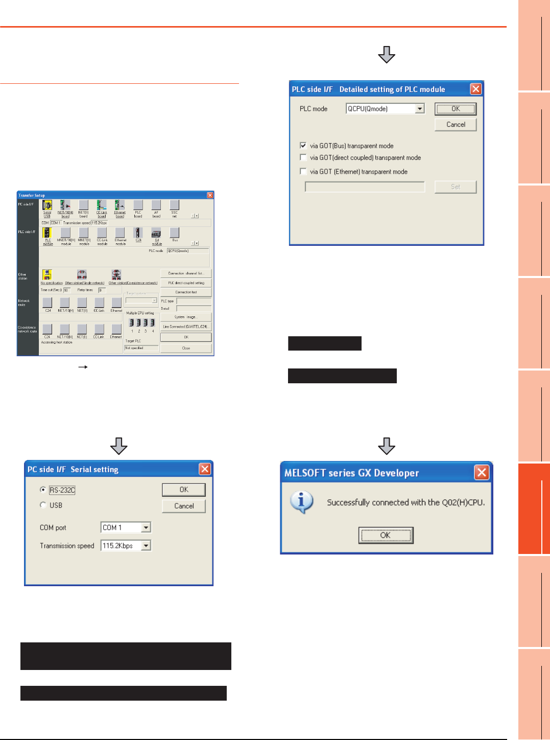
1. Click [Online] [Transfer Setup] in GX Developer.
2. The [Transfer Setup] is displayed.
3. Set the [Transfer Setup]:
PC side I/F : Serial USB (COM)
PLC side I/F : PLC module
Other station : No specification
4. Double-click [Serial] of the PC side I/F to display [PC
side I/F Serial setting].
5. Check-mark either of the following in [PC side I/F
Serial setting].
Mark the [RS-232C] checkbox.
Mark the [USB] checkbox.
When connecting the GOT to PC via modem
When connecting the GOT and PC with serial
When connecting the GOT and PC with USB
(For bus connection)
6. Double-click [PLC module] of the PLC side I/F to
display [PLC side I/F Detailed setting of PLC module].
7. Check-mark either of the following in [PLC side I/F
Detailed setting of PLC module].
[via GOT(Bus) transparent mode]
*1
[via GOT (direct coupled) transparent mode]
*1 This is operation required in the case of using GX Developer
of which version is 8.22Y and above.
8. The screen returns to [Transfer Setup]. Click
[Connection Test] to check if GX Developer has been
connected to the QCPU (Q mode).
Direct CPU connection


