15 - 26
15. INVERTER CONNECTION
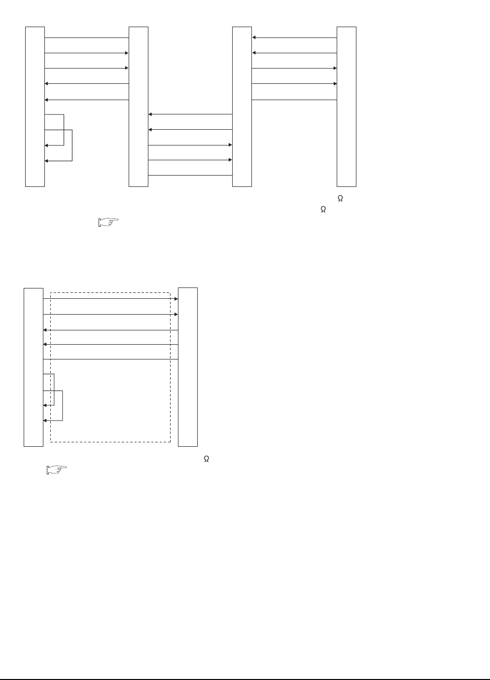
15.3 Connection Diagram
*1 Set the terminator switch built in the farthest inverter from the GOT to ON (100 ).
*2 Set the terminating resistor of GOT side, which will be a terminal, to "330 ".
1.4.3 Terminating resistors of GOT
*1 Set the terminating resistor of the GOT side to "330 ".
1.4.3 Terminating resistors of GOT
RS422 connection diagram 14)
(For GT1030, GT1020)
SG
SDB
SDA
RDB
RDA
RSA
RSB
CSA
CSB
SDA2
SDB2
RDA2
RDB2
GND
Built-in RS-485
terminal block
Station No.0
Built-in RS-485
terminal block
Station No.1
Built-in RS-485
terminal block
*
1
Station No.n
SDA2
SDB2
RDA2
RDB2
GND
GND
RDB1
RDA1
SDB1
SDA1
SDA1
SDB1
RDA1
RDB1
GND
SDA1
SDB1
RDA1
RDB1
GND
SDA2
SDB2
RDA2
RDB2
GND
GOT side
(terminal block)
RS422 connection diagram 15)
(For GT1030, GT1020)
SDA
SDB
RDA
RDB
SG
RSA
RSB
CSA
CSB
RDA
RDB
SDA
SDB
SG
FR-E7TR side
(terminal block)
GOT side
*
1
(terminal block)


